Swash plate compressor

a compressor and plate technology, applied in the direction of machines/engines, liquid fuel engines, positive displacement liquid engines, etc., can solve the problems of difficult to reduce viscosity and difficult to generate heat of lubricating oil, and achieve excellent sliding characteristics and high refrigerating capacity

Inactive Publication Date: 2009-09-03
TOYOTA IND CORP
View PDF29 Cites 6 Cited by
  • Summary
  • Abstract
  • Description
  • Claims
  • Application Information

AI Technical Summary

Benefits of technology

[0009]An object of the invention is to provide a swash plate compressor capable of realizing an excellent sliding characteristic when a drive shaft is rotated at high speed, and a high refrigerating capacity when the drive shaft is rotated at low speed.

Problems solved by technology

Therefore, the lubricating oil in the crank chamber becomes moderate in quantity and so the swash plate does not agitate the lubricating oil so much, so that the lubricating oil is hard to generate heat due to shearing and hard to decrease in viscosity.

Method used


Image

  • Swash plate compressor
  • Swash plate compressor
  • Swash plate compressor

Examples


embodiment 1

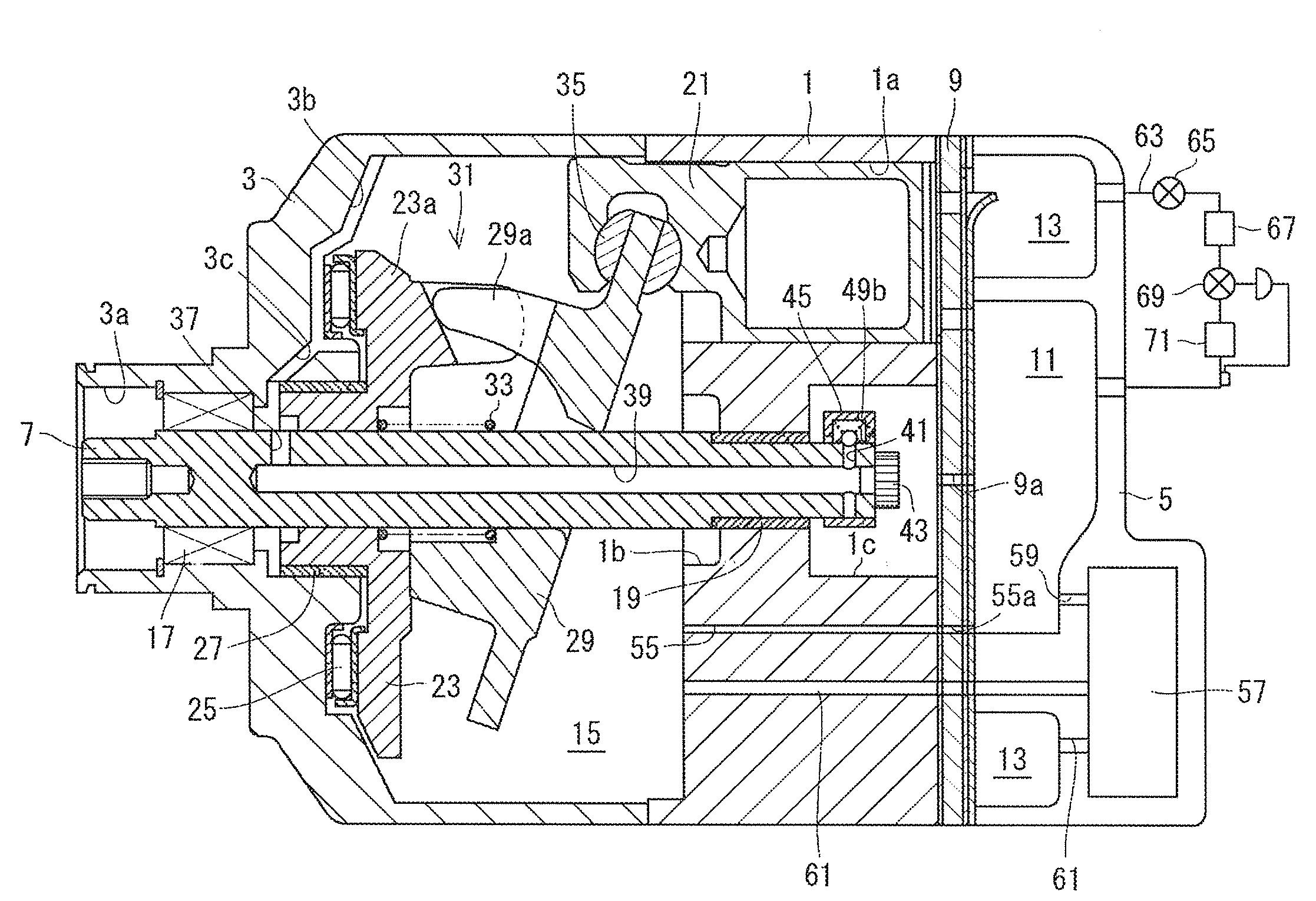
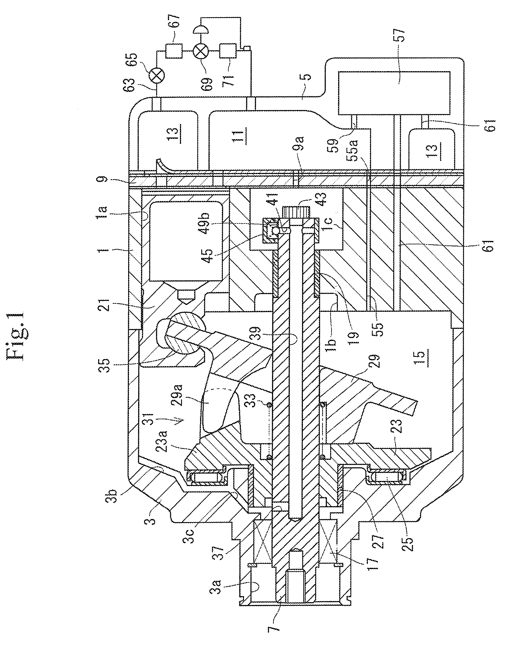
[0027]A swash plate compressor according to EMBODIMENT 1 is of a variable displacement type used for air-conditioning of a vehicle. As shown in FIG. 1, the compressor includes a housing composed of a cylinder block 1, a front housing 3 and a rear housing 5, and a plurality of cylinder bores 1a extending in parallel to an axis of a drive shaft 7 are provided on the cylinder block 1 to extend therethrough. In addition, the left in FIG. 1 indicates the front of the compressor and the right indicates the rear of the compressor.

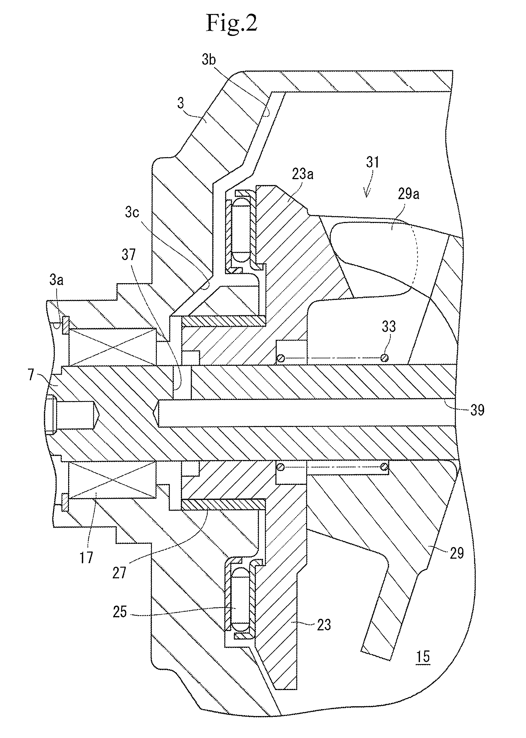
[0028]Formed on the rear housing 5 are a suction chamber 11 and a discharge chamber 13, which are communicated to the respective cylinder bores 1a through a valve unit 9. Also, the front housing 3 and the cylinder block 1 define a crank chamber 15 and axial holes 3a, 1b are formed on the front housing 3 and the cylinder block 1. A shaft seal device 17 is provided in the axial hole 3a. A rubber material is used for the shaft seal device 17. Also, a plain bearing 19...

embodiment 2

[0052]With a swash plate compressor according to EMBODIMENT 2, a plurality of cylinder bores 2a extending in parallel to an axis of a drive shaft 8 are provided on a cylinder block2 to extend therethrough as shown in FIG. 6. Formed on a rear housing 6 are a suction chamber 12 and a discharge chamber 14, which are communicated to the respective cylinder bores 2a through a valve unit 10. Also, a front housing 4 and the cylinder block 2 define a crank chamber 16 and axial holes 4a, 2b are formed on the front housing 4 and the cylinder block 2. A shaft seal device 18 and a plain bearing 20 are provided in the axial hole 4a. A rubber material is used for the shaft seal device 18. Also, a plain bearing 22 is provided in the axial hole 2b. A receiving chamber 2c communicated to the axial hole 2b is formed centrally of a rear end of the cylinder block 2, the receiving chamber 2c being opposed to the valve unit 10.

[0053]The drive shaft 8 is supported by the shaft seal device 18, etc. in a st...


PUM


Abstract

The invention has its object to provide a swash plate compressor capable of realizing demonstration of an excellent sliding characteristic when a drive shaft is rotated at high speed, and of a high refrigerating capacity when the drive shaft is rotated at low speed.
With the swash plate compressor of the invention, an oil guide groove, an oil guide hole, a first hole, an outflow hole, a valve hole, a communication port, a receiving chamber, a throttle hole, and a second hole constitute a release passage. The oil guide groove, the oil guide hole, the first hole, the outflow hole, the valve hole, the communication port, the receiving chamber, and the throttle hole constitute a first passage. Also, the second hole constitute a second passage. A valve mechanism increases a ratio, at which the first passage occupies the release passage, as a drive shaft is increased in rotating speed.

Description

CROSS-REFERENCE TO RELATED APPLICATION[0001]This application claims the benefit of priority to Japanese Patent Application No. 2008-25757, filed on Feb. 5, 2008, No. 2008-38686, filed on Feb. 20, 2008, and No. 2008-52548, filed on Mar. 3, 2008, the contents of which are hereby incorporated herein by reference.BACKGROUND OF THE INVENTION[0002]The present invention relates to a swash plate compressor.[0003]JP-A-8-284816 discloses a conventional swash plate compressor. The swash plate compressor includes a housing composed of a front housing, a cylinder block and a rear housing, and the housing defines a plurality of cylinder bores, a suction chamber, a discharge chamber and a crank chamber therein. The front housing rotatably supports a drive shaft, one end of which is exposed from the front housing. In the crank chamber, a swash plate is supported by the drive shaft so as to vary its inclination angle. Pistons are reciprocatingly received in the respective cylinder bores. Pairs of fr...

Claims


Application Information

Patent Timeline
Patent Type & Authority Applications(United States)
IPC IPC(8): F04B27/18
CPCF04B27/1009F04B27/109F04B2027/1831F04B53/18F04B39/0223
Inventor OGI, TAKESHIMIZUTANI, HIDEKIHIBINO, SOKICHIYAMAMOTO, KENJIKAWAGUCHI, MASAHIROOTA, MASAKIMURASE, MASAKAZUYOKOMACHI, NAOYA
Owner TOYOTA IND CORP
Why Eureka
Try Eureka