Pressure sensor

a technology of pressure sensor and pressure sensor, which is applied in the direction of fluid pressure measurement using piezoelectric devices, instruments, measurement devices, etc., can solve the problems of inapplicability of pressure sensor using oil b>110/b> according to related art to measurement of pressure of pure liquid that dislikes foreign substances, and the measurement accuracy of pressure detection is high. , the effect of large thermal expansion coefficien

Inactive Publication Date: 2009-10-01
SEIKO EPSON CORP
View PDF17 Cites 9 Cited by
  • Summary
  • Abstract
  • Description
  • Claims
  • Application Information

AI Technical Summary

Benefits of technology

[0023]An advantage of the present invention is to provide a pressure sensor that does not use oil as a pressure receiving medium thereinside, is miniaturized with a force transmitting member of which a structure is simplified, and has high measurement accuracy of pressure detection.
[0024]The invention can be achieved by following aspects.
[0025]A pressure sensor according to a first aspect of the invention includes: a housing; an attachment portion coupled to the housing and having a pressure input orifice; a diaphragm sealing the pressure input orifice of the attachment portion and having a first surface that is a pressure receiving surface; and a pressure sensitive unit having a detecting axis in a direction in which a force is detected. In the sensor, an end of the pressure sensitive unit is connected to a central area of a second surface of the diaphragm, another end of the pressure sensitive unit is connected to the housing, and the detecting axis is approximately orthogonal to the pressure receiving surface.
[0026]According to the first as

Problems solved by technology

Therefore, thermal distortion occurs in the components constituting the pressure sensor due to a temperature change.
Such thermal distortion works on the double-ended tuning fork resonator 109 as unwanted stress, resulting in an error of a measured pressure value.
Therefore, the pressure sensor using the oil 110 according to related art is not applicable to measurement of pressure of a pure liquid that dislikes foreign substances.
Furthermore, the pressure sensor 101 of related art includes the force transmitting member 105 having a complicated structure, thereby being difficult to be miniaturized.
In addition, the force transmitting member 105 requires a flexible hinge having a slim constriction so as to be an expensive component, thereby disadvantageously increasing a cost for manufacturing a pressure sensor.
If bubbles are generated in the oil, the oil can not stably transmit a force through the pedestal to the double-ended tuning fork resonator, resulting in an error of the pressure measurement.
Therefore, pre

Method used


Image

  • Pressure sensor
  • Pressure sensor
  • Pressure sensor

Examples


first embodiment

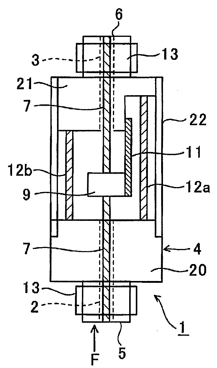
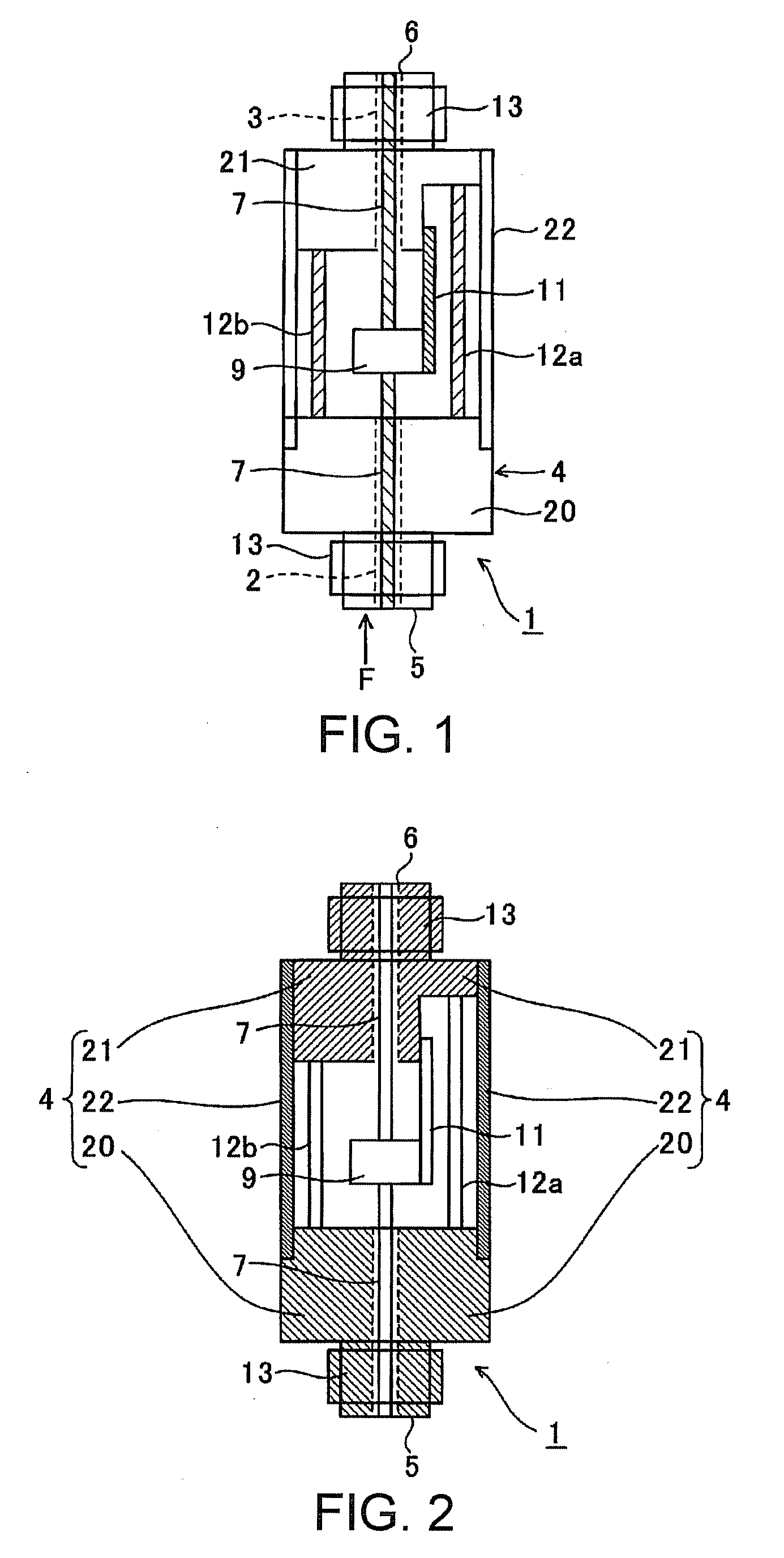
[0075]FIG. 1 is a schematic view showing a structure of a pressure sensor according to a first embodiment of the invention.

[0076]This pressure sensor 1 shown in FIG. 1 has a first pressure input orifice 2 and a second pressure input orifice 3 that are used for vacuuming the inside and are disposed to be opposed to each other. Further, the pressure sensor 1 includes a housing 4 for housing components described later. On an end portion of the first pressure input orifice 2, a first diaphragm (a pressure receiving diaphragm) 5 is attached and exposed to outside. The first diaphragm 5 bends depending on a pressure of a liquid that is a measurement object. On an end portion of the second pressure input orifice 3, a second diaphragm (an atmospheric pressure setting diaphragm) 6 is attached. The second diaphragm 6 bends depending on atmospheric pressure. Between the first diaphragm 5 and the second diaphragm 6, a center shaft 7 is disposed as a force transmitting unit and is exposed to out...

second embodiment

[0100]A pressure sensor according to a second embodiment of the invention will now be described.

[0101]FIG. 5 is a schematic view showing a structure of a pressure sensor according to the second embodiment of the invention. The identical numerals are given to the same components as those described above with reference to FIG. 1 and those descriptions will be omitted.

[0102]In the pressure sensor of the first embodiment, the pressure receiving medium with respect to atmospheric pressure is connected with the movable member 9 so as to measure a relative pressure represented by using the atmospheric pressure as a reference of zero. While, in the pressure sensor of the second embodiment, only a pressure receiving medium with respect to a liquid that is a measurement object is connected with the movable member 9 so as to measure an absolute pressure measured with a vacuum state as a reference of zero and a pressure receiving medium with respect to atmospheric pressure is removed.

[0103]In a...

third embodiment

[0109]FIG. 6 is a schematic view showing a pressure sensor 40 according to a third embodiment. FIG. 7 is a perspective view showing a major component of the pressure sensor. FIG. 8 is a perspective view showing a fracture of a part of the pressure sensor. An example shown in the figures is a modification of the pressure sensor for detecting the differential pressure, described in the first embodiment.

[0110]The pressure sensor 40 includes a housing 42 that is a hollow cylindrical chassis. This housing 42 is composed of a flange end plate 44 as a first case (a lower end plate), a hermetic terminal board 46 as a second case (an upper end plate), and a cylinder sidewall 48 as a third case surrounding the circumference of the end plates that are disposed at a distance, so as to be a hollow airtight container. On the flange end plate 44 and the hermetic terminal board 46, a first pressure input orifice 47 and a second pressure input orifice 49 communicating with an internal space are resp...


PUM


Abstract

A pressure sensor includes: a housing; an attachment portion coupled to the housing and having a pressure input orifice; a diaphragm sealing the pressure input orifice of the attachment portion and having a first surface that is a pressure receiving surface; and a pressure sensitive unit having a detecting axis in a direction in which a force is detected. In the sensor, an end of the pressure sensitive unit is connected to a central area of a second surface of the diaphragm, another end of the pressure sensitive unit is connected to the housing, and the detecting axis is approximately orthogonal to the pressure receiving surface.

Description

BACKGROUND[0001]1. Technical Field[0002]The present invention relates to a pressure sensor that does not use oil as a pressure receiving medium and therefore is suitable for broadening a scope of application thereof.[0003]2. Related Art[0004]Pressure sensors that use a piezoelectric resonator as a pressure sensitive element are known as a water pressure gauge, an air gauge, and a differential pressure gauge. The piezoelectric resonator includes, for instance, an electrode pattern on a planar piezoelectric substrate, and a direction in which a force is detected set to be a detecting axis. When pressure is applied in the direction of the detecting axis, a resonance frequency of the piezoelectric resonator changes and the pressure is detected by using the fluctuation in the resonance frequency. JP-A-56-119519, JP-A-64-9331, and JP-A-2-228534, as a first, second, and third examples, disclose a pressure sensor including a piezoelectric resonator as a pressure sensitive element. When a pr...

Claims


Application Information

Patent Timeline
IPC IPC(8): G01L9/08
CPCG01L9/0033G01L13/023G01L9/008
Inventor MOTOYAMA, HISAO
Owner SEIKO EPSON CORP
Why Eureka
Try Eureka