
Battery clamp for use with top post and side post batteries and methods for using the same

Active Publication Date: 2009-10-01
AUTO METER PROD INC
View PDF1 Cites 70 Cited by
  • Summary
  • Abstract
  • Description
  • Claims
  • Application Information

AI Technical Summary

Problems solved by technology

A poor connection can result in damage to the battery, damage to the charging / testing device, injury to the operator, and it can impact the accuracy of test results.
For example, poor connections can lead to the generation of heat, which can cause the battery terminals to melt and possibly cause the battery to explode in some cases.
While connecting standard battery clamps onto the steel bolts is possible, it is difficult and less accurate than other methods.
However, lead adapter posts are small and are easily lost or misplaced in automotive repair / testing shops.
Typically, when technicians lose or misplace their lead adapter posts, they often substitute a standard steel bolt to provide a method of attaching the standard battery clamps; however, the steel bolts only contact the threaded bore portion of the side post terminal.
Such an arrangement can yield both inaccurate battery test results and also generate significant amounts of heat that can melt and destroy the side post battery 200.

Method used


Image

  • Battery clamp for use with top post and side post batteries and methods for using the same
  • Battery clamp for use with top post and side post batteries and methods for using the same
  • Battery clamp for use with top post and side post batteries and methods for using the same

Examples


embodiment 1

Alternative Embodiment 1

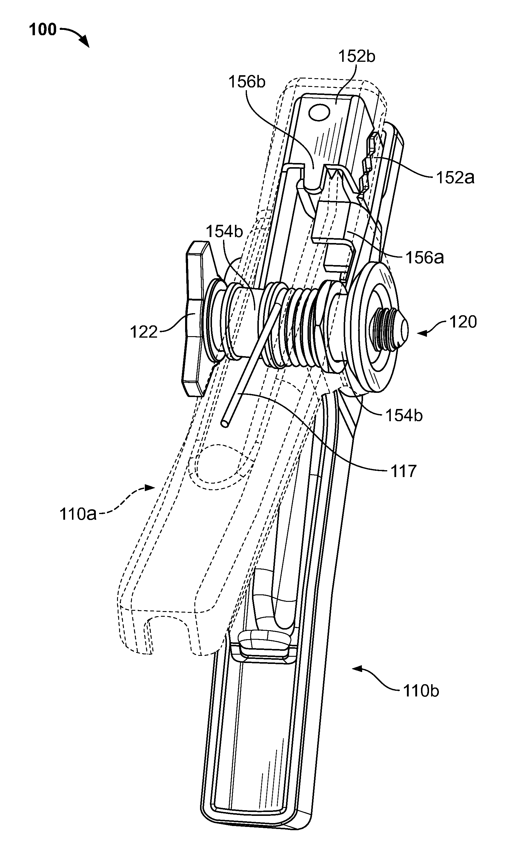
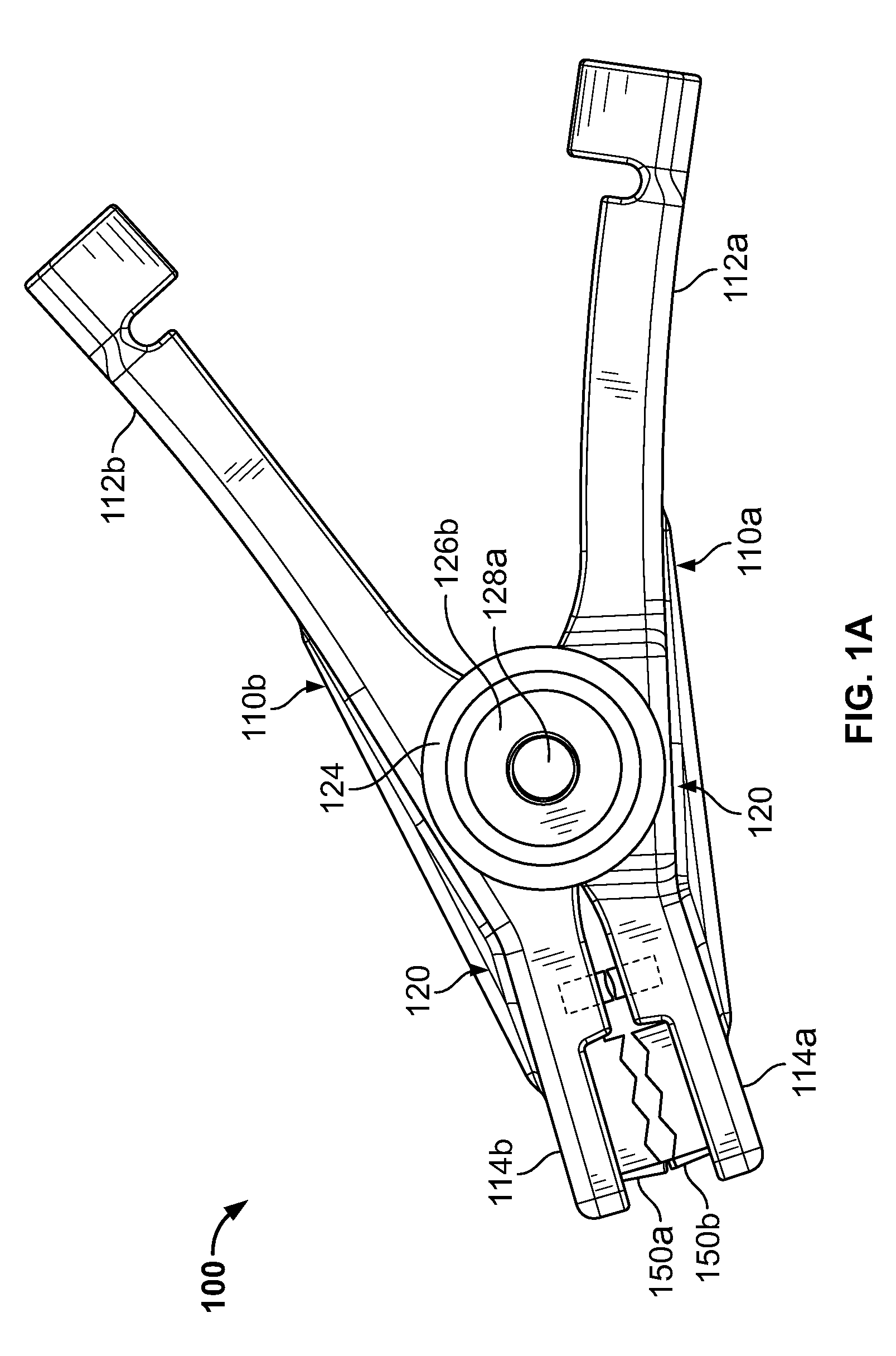
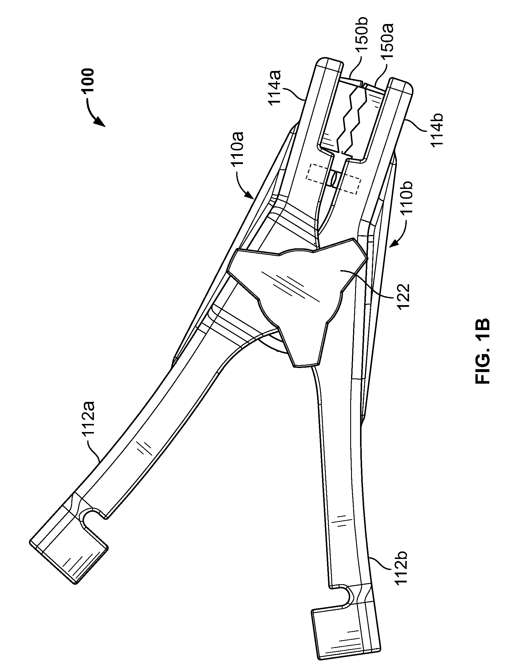
[0125]A battery clamp for use with (a) batteries with top post terminal connections and (b) batteries with side post terminal connections includes a first and second jaw handle, each of the first and second jaw handles having a handle portion and a clamping portion, the first and second jaw handles being pivotally coupled together, the jaw handles being biased with the clamping portions being in a closed position; a first and second jaw member, each of the jaw members having a jaw clamp portion, a jaw pivot portion, and a jaw wire connection portion, the jaw pivot portion of the first jaw member being pivotally coupled to the first and second jaw handles, the jaw pivot portion of the second jaw member being pivotally coupled to the first and second jaw handles; a load pad electrically coupled to the first jaw member, the load pad having an aperture; and a volt rod electrically coupled to the second jaw member, a portion of the volt rod protruding through the ...

embodiment 2

Alternative Embodiment 2

[0126]The battery clamp of alternative embodiment 1, wherein the first jaw handle further includes a first aperture and a second aperture, and the second jaw handle further includes a third aperture and a fourth aperture.

embodiment 3

Alternative Embodiment 3

[0127]The battery clamp of alternative embodiment 2, wherein the first aperture and the third aperture are positioned adjacent each other and form a first pivot point, and the second aperture and the fourth aperture are positioned adjacent each other and form a second pivot point.


PUM


Abstract

A battery clamp for use with (a) batteries with top post terminal connections and (b) batteries with side post terminal connections includes a first jaw handle and a second jaw handle. The jaw handles each have a handle portion and a clamping portion. The jaw handles are pivotally coupled to each other and are biased with the clamping portions in a closed position. The battery clamp further includes a first jaw member and a second jaw member. The jaw members have a jaw clamp portion, a jaw pivot portion, and a jaw wire portion. The jaw pivot portion of the first jaw member and the jaw pivot portion of the second jaw member are both pivotally coupled to the jaw handles. The battery clamp further includes a load pad and a volt rod. The load pad has an aperture and is coupled to the first jaw member. The volt rod is coupled to the second jaw member and protrudes through the aperture of the load pad.

Description

CROSS-REFERENCE TO RELATED APPLICATIONS[0001]This application claims the benefit of U.S. Provisional Application No. 61 / 040,039, filed Mar. 27, 2008, and U.S. Provisional Application No. 61 / 091,964, filed Aug. 26, 2008, both of which are hereby incorporated by reference herein in their entireties.FIELD OF THE INVENTION[0002]The field of the invention relates generally to battery clamps for testing and / or charging batteries with top post and / or side post terminal connections. More particularly, the present invention relates to battery clamps with side post adapters and methods of using the same to charge and / or test batteries.BACKGROUND OF THE INVENTION[0003]In the automotive battery field, automotive technicians use battery clamps to electrically connect a battery to a charging / testing device. According to some embodiments, it is important for these battery clamps to have a secure physical and a secure electrical connection with the battery's terminals. A poor connection can result ...

Claims


Application Information

Patent Timeline
IPC IPC(8): H01R4/48
CPCH01R11/24
Inventor GATHMAN, MICHAEL R.SMITH, RICHARD S.
Owner AUTO METER PROD INC
Learn More