Sound post setter

a sound post and setter technology, applied in the field of sound post setters, can solve the problems of not providing the control necessary to tightly wedge and/or turn the sound post so as to meet the angles of the top and the rear surfaces, and hindering the installation or replacement of the sound pos

Inactive Publication Date: 2009-11-12
BETER GEORGE
View PDF9 Cites 6 Cited by
  • Summary
  • Abstract
  • Description
  • Claims
  • Application Information

AI Technical Summary

Problems solved by technology

These physical characteristics present obstacles to a musician or repair-person wanting to install or replace a sound post.
Although these devices permit installation th

Method used


Image

  • Sound post setter
  • Sound post setter
  • Sound post setter

Examples


Embodiment Construction

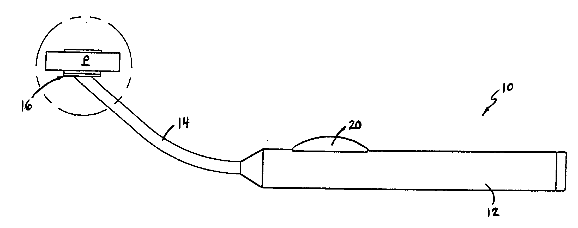
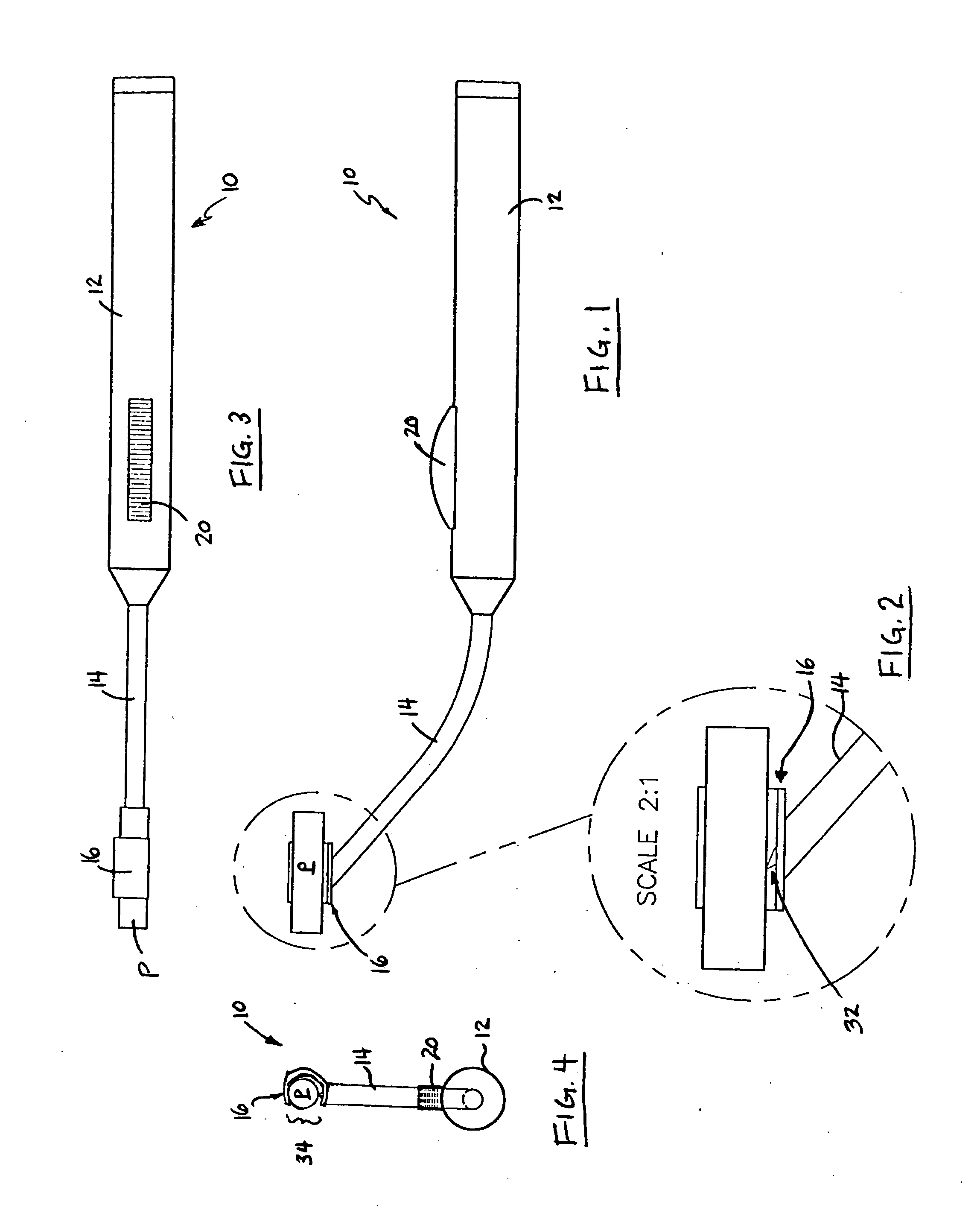
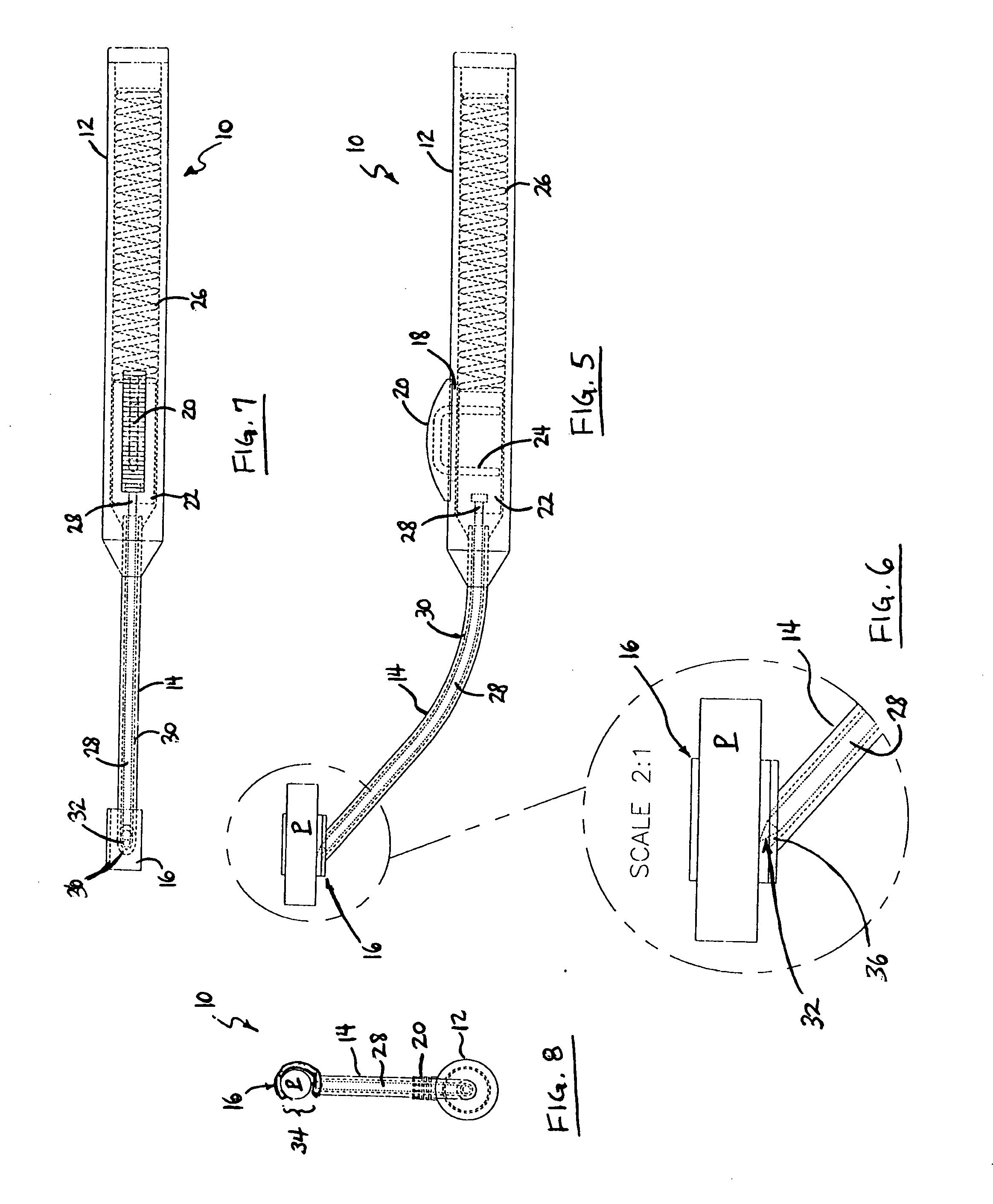
[0025]Generally, the sound post referenced herein shall be denoted as “P” unless otherwise indicated. It is intended, and envisioned, that a sound post is configured in keeping with the current understanding in the art, having a generally solid cylindrical shape and normally formed of a wood product (e.g. spruce) utilized in wooden stringed-instruments, such as a viola, violin or cello (though not necessarily exhaustive). Although the axial length of the sound post “P” may vary in accordance with the specific instrument, usually the smallest sound post “P” measures approximately six centimeters, with longer lengths available for larger instruments. The terminal ends of the sound post “P” may be planar or angular, or may be tailored to be complementary to the inner surfaces of the top surface and rear surface, respectively, of the wood instrument. The specific placement of the sound post “P” conforms to the accepted practices, including placement along the treble side of the instrume...


PUM


Abstract

A device for installing a sound post in a musical instrument comprises a handle and an arm depending from the handle, the handle and arm defining a passageway therein. The device includes a cradle depending from the arm, the cradle having an opening formed at the junction of the cradle and the arm. The device also includes a cable having a nib at an end, the cable traversing the passageway. The device also includes a lever or knob moving the cable to advance or retract the nib through the opening.

Description

FIELD OF INVENTION[0001]This application discloses claims and embodiments generally related to a device for installing a sound post in a musical instrument, and more particularly, a device having a retracting nib or spike for temporarily holding the sound post during installation.BACKGROUND OF THE INVENTION[0002]A number of stringed-instruments fabricated from wood possess a solid cylindrical element referred to as a sound post, including violins, violas and cellos. Generally, the sound post is a solid cylinder of wood (e.g. spruce) and is used to support the belly of such an instrument. The sound post is impinged between the top and the rear of the wood instrument and within the belly of the instrument. The sound post is not glued, adhered or mechanically affixed between the front and rear, but is held in position by the tension of the front and rear portions of the instrument, generally as a result of the pull of the strings on the instrument, and by the generally complementary an...

Claims


Application Information

Patent Timeline
IPC IPC(8): G10D1/02
CPCG10D3/02
Inventor BETER, GEORGE
Owner BETER GEORGE
Why Eureka
Try Eureka