Wireless communication apparatus and a reception method involving frequency hopping

a technology of wireless communication and frequency hopping, which is applied in the direction of polarisation/directional diversity, dc level restoring means or bias distortion correction, baseband system details, etc., can solve the problems of increasing the cost, increasing the number of rf bpfs, etc., and achieves the effect of increasing speed and capacity

Inactive Publication Date: 2009-11-12
RENESAS ELECTRONICS CORP
View PDF2 Cites 30 Cited by
  • Summary
  • Abstract
  • Description
  • Claims
  • Application Information

AI Technical Summary

Benefits of technology

[0064]According to the present invention, in the receiver of the wireless communication apparatus in the direct conversion receiving system in which a packet is transmitted or received while performing frequency hopping for each symbol and demodulation is started by performing carrier sensing at the beginning of the packet on the side of the receiver, correlation detection (CCA: Clear Channel Assessment detection) at the preamble part at the beginning of the packet received through the frequency hopping, or an operation from carrier sensing to synchronization and start of hopping, and further AGC (Auto Gain Control) / AFC (Auto Frequency Control) / synchronization establishment can be stably performed at high speed. The problem of occurrence of DC offset jump immediately after the frequency hopping can be thereby solved.
[0065]Further, according to the present invention, a further increase in speed and capacity can be obtained by a MIMO space division multiplexing method.

Problems solved by technology

Thus, RF detection for each frequency hopping is needed, thereby bringing about an increase in the number of RF BPFs and an increase in the circuit size due to the detection circuit configuration for each RF signal, an increase in the cost, and an increase in power consumption.
Thus, once the DC offset jump has occurred, it becomes difficult to improve or solve degradation in the receiver.

Method used


Image

  • Wireless communication apparatus and a reception method involving frequency hopping
  • Wireless communication apparatus and a reception method involving frequency hopping
  • Wireless communication apparatus and a reception method involving frequency hopping

Examples


Embodiment Construction

[0076]The principles of the present invention, contrast with related arts (Patent Documents) and specific exemplary embodiments will be described in the below.

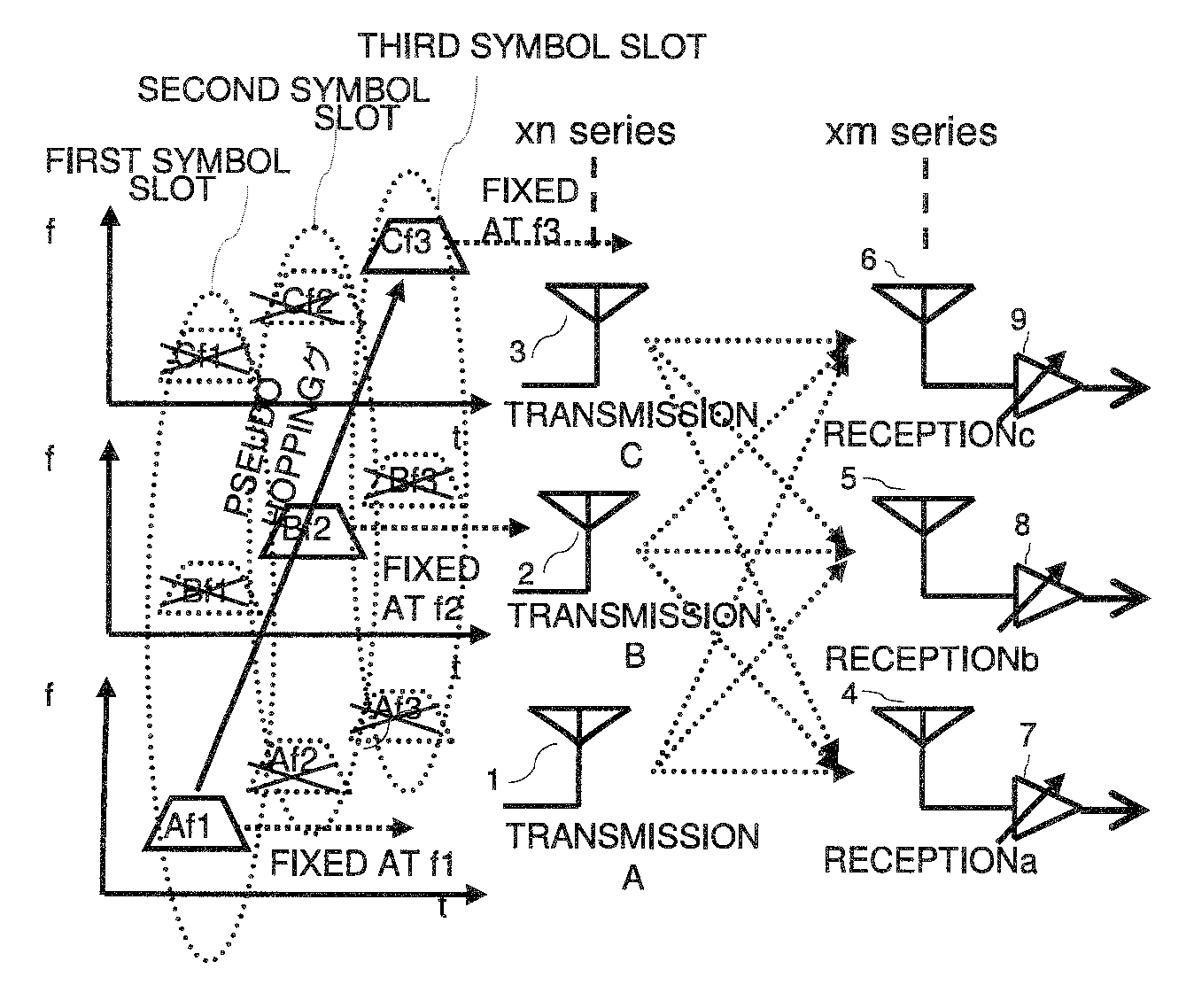
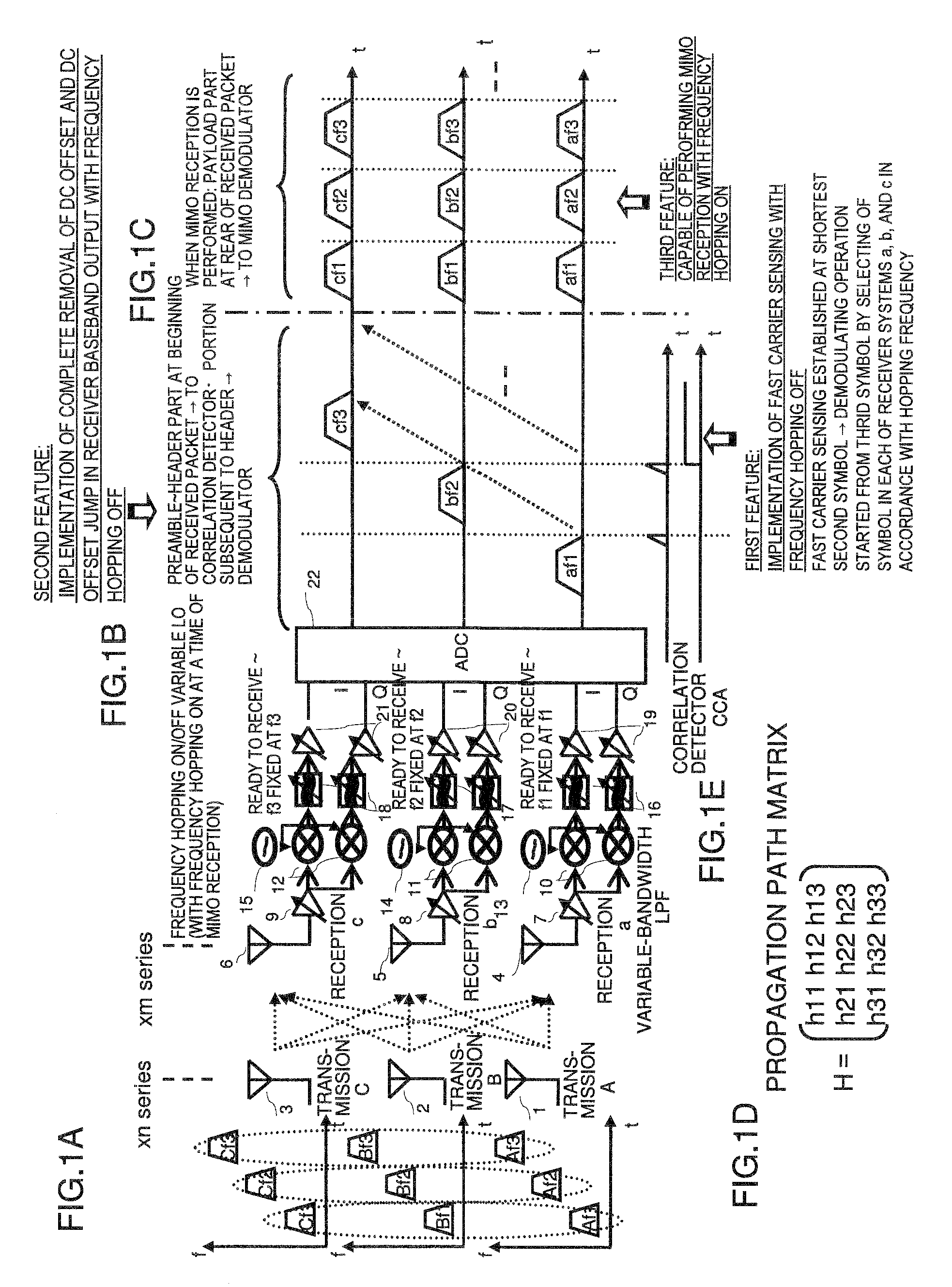
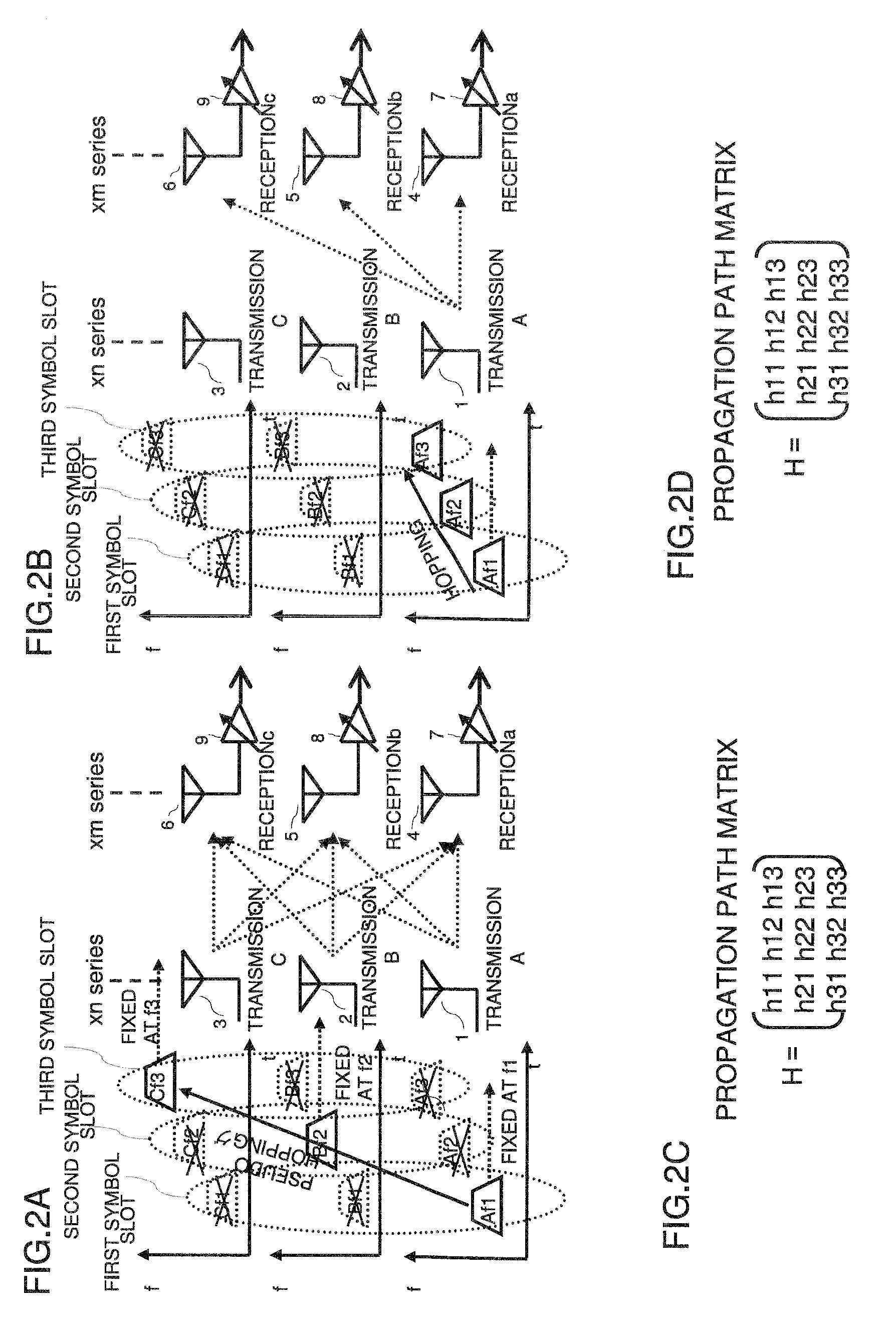
[0077]A wireless communication apparatus according to the present invention (such as a Multi Band OFDM (Orthogonal Frequency Division Multiplexing) UWB (Ultra Wide Band) system compliant with a WiMedia standard, used as a PHY (physical layer) in Wireless USB, or the like) adopts a direct conversion receiving system, in which a packet is transmitted or received while performing frequency hopping for each symbol, and demodulation is started by performing carrier sensing at the beginning of the packet on the side of a receiver. The wireless communication apparatus is configured so that the LO (Local Oscillation) frequency in each of a plurality of receiving systems is fixed at each hopping frequency and each receiving system is brought into a ready state for reception. The number of the receiving systems conforms to the number of...


PUM


Abstract

Disclosed is a receiver of a direct conversion receiving scheme in which a packet is transmitted or received while performing frequency hopping for each symbol and demodulation is started by carrier sensing at the beginning of the packet, which performs demodulation without hopping frequencies of LOs of receiving systems to reliably execute fast carrier sensing and hopping synchronization at the beginning of the packet and remove the DC offset jump. At a time of demodulation of a payload part, the frequencies of LOs of the receiving system are hopped to allow a transition of MIMO. Further, by concurrently using complex bandpass filters while fixing all the LOs at a center LO frequency, complete removal of the DC offset jump over the entire length of the packet and MIMO can be simultaneously implemented.

Description

REFERENCE TO RELATED APPLICATION[0001]This application is based upon and claims the benefit of the priority of Japanese patent application No. 2008-123513 filed on May 9, 2008, the disclosure of which is incorporated herein in its entirety by reference thereto.TECHNICAL FIELD[0002]The present invention relates to a wireless communication apparatus and a reception method involving frequency hopping. More specifically, the invention relates to a wireless communication apparatus having a receiver configuration and a reception method, suitable for use in a direct conversion receiving system. In the direct conversion receiving system, a packet is transmitted or received while performing frequency hopping for each symbol and demodulation on a receiver side is started by performing carrier sensing at the beginning of the packet.BACKGROUND[0003]In a receiver of a wireless communication apparatus which adopts the direct conversion receiving scheme (such as a Multi Band OFDM (Orthogonal Frequ...

Claims


Application Information

Patent Timeline
Patent Type & Authority Applications(United States)
IPC IPC(8): H04B1/713H04B1/30H04B7/04H04J11/00H04J99/00
CPCH04B1/713H04L27/2647H04L25/06
Inventor MOCHIZUKI, TAKUJI
Owner RENESAS ELECTRONICS CORP
Why Eureka
Try Eureka