
Control of combined cycle power generation system
- Summary
- Abstract
- Description
- Claims
- Application Information
AI Technical Summary
Benefits of technology
Problems solved by technology
Method used
Image

Examples
Embodiment Construction
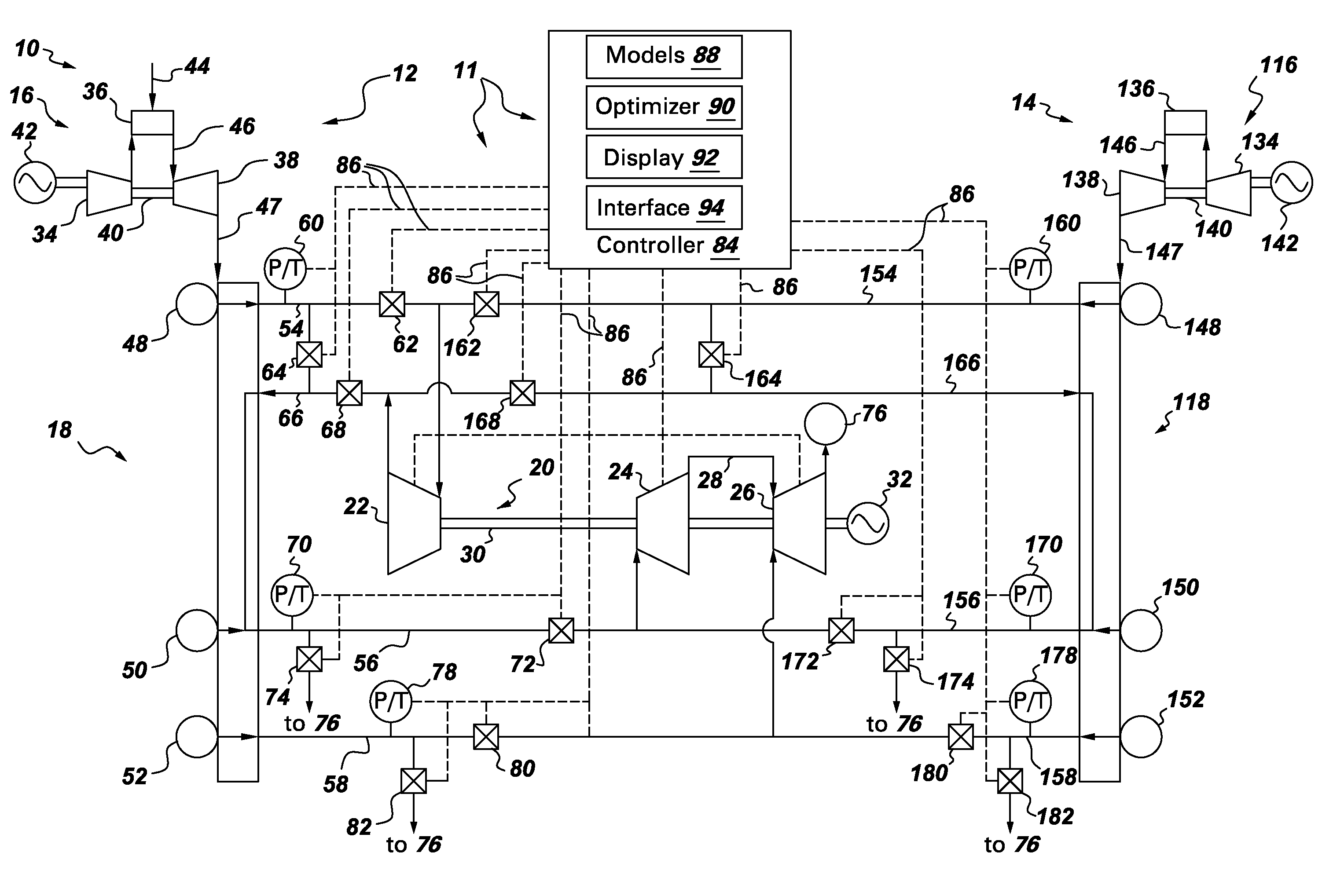
[0017]FIG. 1 is a schematic diagram of an exemplary combined-cycle power generation system 10. Generally, system 10 includes a lead side 12 and a lag side 14. Lead side 12 includes a gas turbine engine (GT) 16 that is coupled in flow communication with a heat recovery steam generator (HRSG) 18. HRSG18 is coupled in flow communication with a steam turbine assembly (ST) 20. ST 20 includes a high pressure (HP) turbine 22, an intermediate pressure (IP) turbine 24, and a low pressure (LP) turbine 26. IP turbine 24 is coupled in flow communication to LP turbine 26 using an IP-to-LP crossover header 28. Turbines 22, 24, and 26 are each coupled to a rotor shaft 30 that is also coupled to an electric generator 32.
[0018]In the embodiment of FIG. 1, lead GT 16 includes a compressor 34, a combustor 36, and a turbine 38. Compressor 34 is coupled in flow communication with combustor 36, which is coupled in flow communication upstream from turbine 38. Compressor 34 and turbine 38 are each coupled ...
PUM
 Abstract
Description
Claims
Application Information