Variable pitch electrode array

a variable-pitch electrode array and electrode array technology, applied in the field of electrode arrays, can solve the problems of increasing the amount of electrical current required to stimulate the perception of light, not how the human body is arranged, etc., and achieve the effect of maximizing the resolution

Active Publication Date: 2009-12-31
CORTIGENT INC +1
View PDF26 Cites 49 Cited by
  • Summary
  • Abstract
  • Description
  • Claims
  • Application Information

AI Technical Summary

Benefits of technology

[0007]The present invention is an implantable electrode array having electrodes with variable pitch and variable size. Electrode arrays of the prior art provide electrodes with a common spacing and size. However, this is not how the human body is arranged. As an example, the retina has closely spaced retinal light receptors near the fovea. The light receptors are spaced farther apart, farther away from the fovea, near the periphery of the retina. Further, the amount of electrical current required to stimulate the perception of light increases with distance from the fovea. Hence, larger electrodes are required to transfer the necessary current farther away from the fovea. By placing small, closely spaced low power electrode near the fovea, and larger widely spaced electrode at the periphery, resolution is maximized.

Problems solved by technology

However, this is not how the human body is arranged.
Further, the amount of electrical current required to stimulate the perception of light increases with distance from the fovea.

Method used


Image

  • Variable pitch electrode array
  • Variable pitch electrode array
  • Variable pitch electrode array

Examples


Embodiment Construction

[0012]The following description is of the best mode presently contemplated for carrying out the invention. This description is not to be taken in a limiting sense, but is made merely for the purpose of describing the general principles of the invention. The scope of the invention should be determined with reference to the claims.

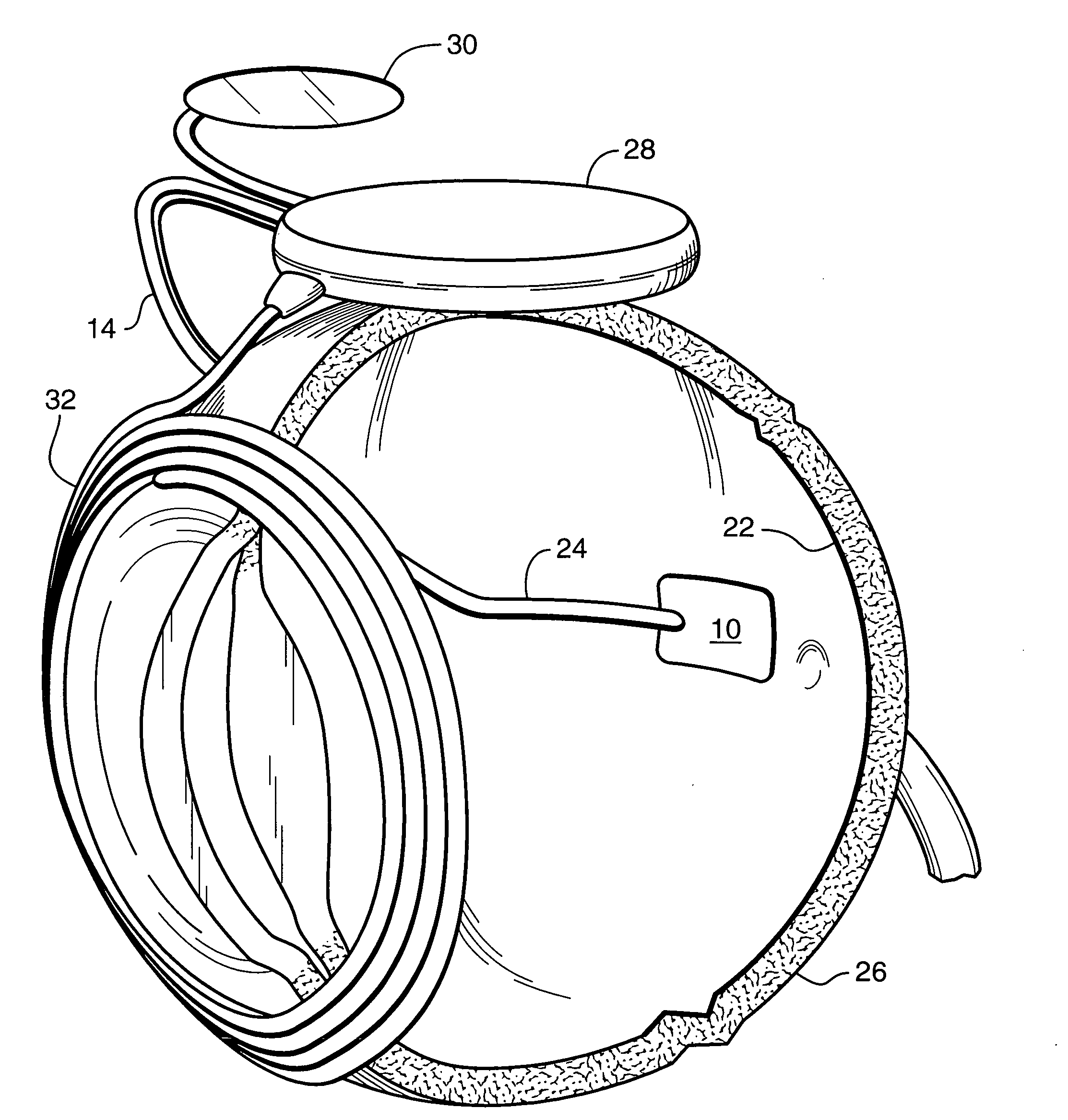
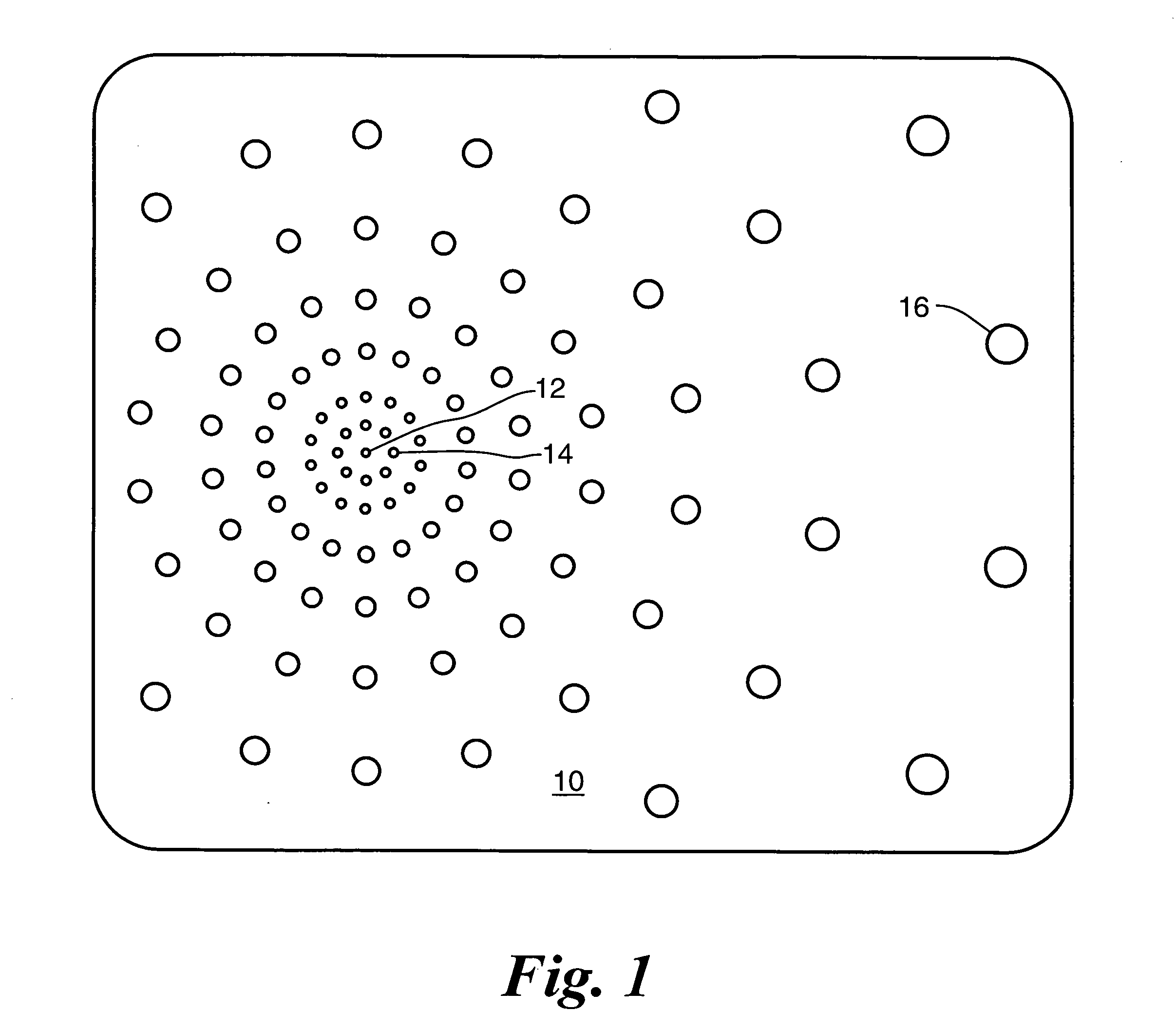
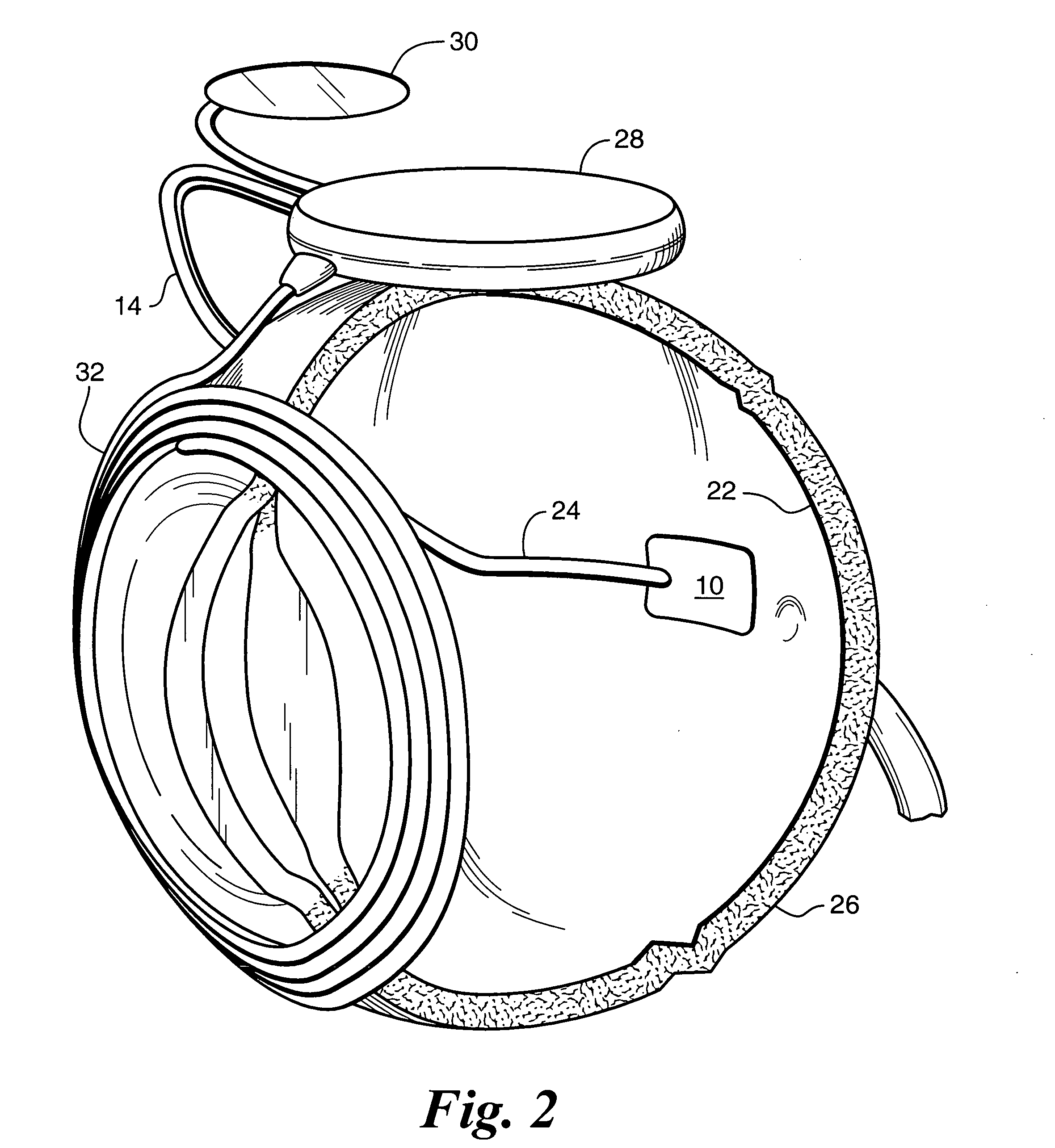
[0013]The present invention provides an array of variable pitch, variable size electrodes. FIG. 1 shows the invention applied to a retinal stimulator for artificial sight. Electrodes on the preferred retinal electrode array 10 begin very small and close together with a center electrode 12 at the fovea. A first circle of electrodes 14 approximately 10 microns in width are placed 5 microns apart. The size and pitch of the electrodes increases proportionally moving away from the fovea. It is not necessary that the fovea be at the center of the electrode array. The preferred electrode array extends further from the fovea in the direction opposite from the optic ...


PUM


Abstract

The present invention is an implantable electrode array having electrodes with variable pitch and variable size. Electrode arrays of the prior art provide electrodes with a common spacing and size. However, this is not how the human body is arranged. As an example, the retina has closely spaced retinal receptors near the fovea. Those receptors are spaced farther apart, farther away from the fovea. Further, the amount of electrical current required to stimulate the perception of light increases with distance from the fovea. Hence, larger electrodes are required to transfer the necessary current farther away from the fovea.

Description

CROSS REFERENCE TO RELATED APPLICATION(S)[0001]This application is a divisional of Application Ser. No. 10 / 112,801, filed Mar. 28, 2002, the disclosures of which is incorporated herein by reference, as if fully stated here, for all purposes.GOVERNMENT RIGHTS NOTICE[0002]This invention was made with government support under grant No. R24EY12893-01, awarded by the National Institutes of Health. The government has certain rights in the invention.FIELD OF THE INVENTION[0003]The present invention is generally directed to electrode arrays, and more particularly to implantable electrode arrays for medical devices.BACKGROUND OF THE INVENTION[0004]Arrays of electrodes for neural stimulation are commonly used for a variety of purposes. Some examples include: U.S. Pat. No. 3,699,970 to Brindley describes an array of cortical electrodes for visual stimulation. Each electrode is attached to a separate inductive coil for signal and power. U.S. Pat. No. 4,573,481 to Bullara describes a helical ele...

Claims


Application Information

Patent Timeline
Patent Type & Authority Applications(United States)
IPC IPC(8): A61N1/05
CPCA61B2562/0209A61N1/0543A61N1/05A61B2562/046A61N1/0531
Inventor GREENBERG, ROBERTWILLIAMSON, RICHARDHUMAYAN, MARK
Owner CORTIGENT INC
Why Eureka
Try Eureka