Push-pin fastening system

a technology of push-pin and fastener, which is applied in the direction of pins, fastening means, screws, etc., can solve the problems of loose fit, risk of separation, and maintain the centering of the fastener within the apertur

Active Publication Date: 2010-01-28
ZEPHYROS INC
View PDF31 Cites 94 Cited by
  • Summary
  • Abstract
  • Description
  • Claims
  • Application Information

AI Technical Summary

Benefits of technology

[0016]In another aspect, the present invention contemplates a method of using a fastening system comprising: providing a vehicle component having one or more substrate layers wherein the substrate layers have a top and bottom; providing a trapezoidal shaped aperture within each of the one or more substrate layers, wherein the aperture has two non-parallel opposing walls so that the aperture is non-symmetrical across one axis; providing a fastener for insertion through the aperture, wherein the fastener includes: a cap surface; a shank extending from the cap surface in the direction of a longitudinal axis wherein the shank includes four side walls disposed about the longitudinal axis and the four side walls include two non-parallel opposing walls so that the shape of the fastener corresponds to the shape of the aperture; a plurality of flexible wings extending outwardly from at least one of the four side walls; inserting the fastener into the aperture such that at least one flexible wing is in contact with the top of the one or more substrate layers and at least one flexible wing is in contact with the bottom of the one or more substrate layers.

Problems solved by technology

A particular challenge in using these types of fasteners, especially in the automotive field, lies in providing a fastener that will afford the most secure attachment in combination with the simplest insertion process and fewest additional parts or insertion steps.
Often, improper insertion direction results in loose fit and the risk of separation.
Other problems include the difficulty in maintaining the fastener centered within an aperture so that it may have less of a tendency to loosen within the aperture or slip out of the aperture completely.
A fastener with a basic rounded shank runs the risk of separation with any aperture that is not circular and of similar diameter.
One problem that arises with the use of some existing fastener structures is that their size and shape do not allow for ideal fit and security within an aperture.
This unfortunately results in slipping and disengagement of the fasteners.
Further, most push-pin fasteners are not capable of providing secure fastening to a multi-layer substrate, nor do they have the capability of fastening substrates with a wide variety of thicknesses with one standard fastener.
As another problem, many push-pin fasteners provide no means to ensure that the fastener is inserted in the ideal position to ensure maximum secure fit.
As such, fasteners that are inserted upside-down, sideways or at any other imperfect position, are again subject to rotation, slippage, disengagement, or at the very least, abnormally difficult insertion.
Those fasteners that are circular in nature and thus not subject to improper insertion direction often fail to fit securely within any non-circular aperture, resulting in slippage and disengagement.
A further issue with many fasteners is that multiple fasteners or additional attachments are often required to prevent slippage, disengagement, or a fastened part from twisting about a fastener.
This results in increased parts, labor, and maintenance.

Method used


Image

  • Push-pin fastening system
  • Push-pin fastening system
  • Push-pin fastening system

Examples


Embodiment Construction

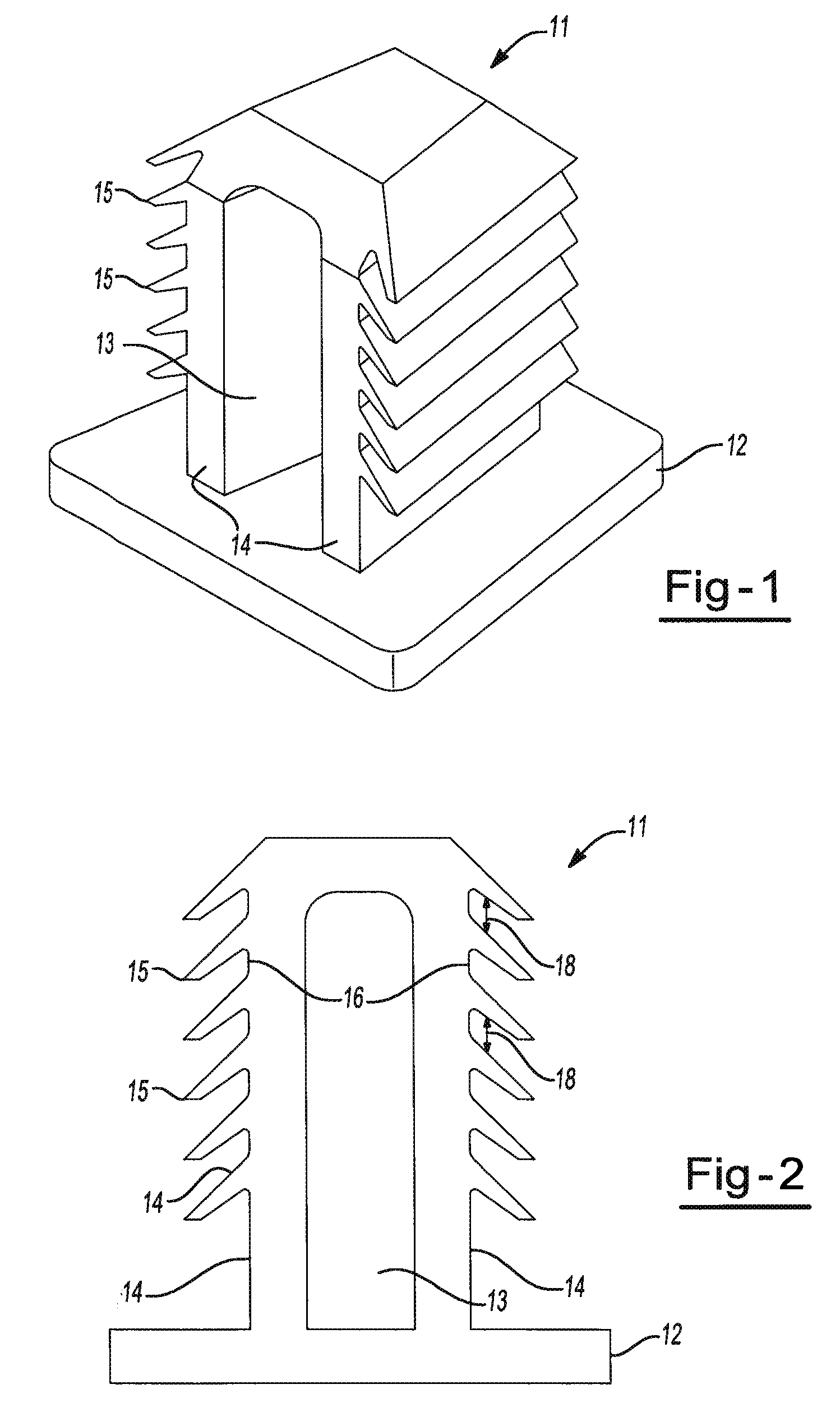
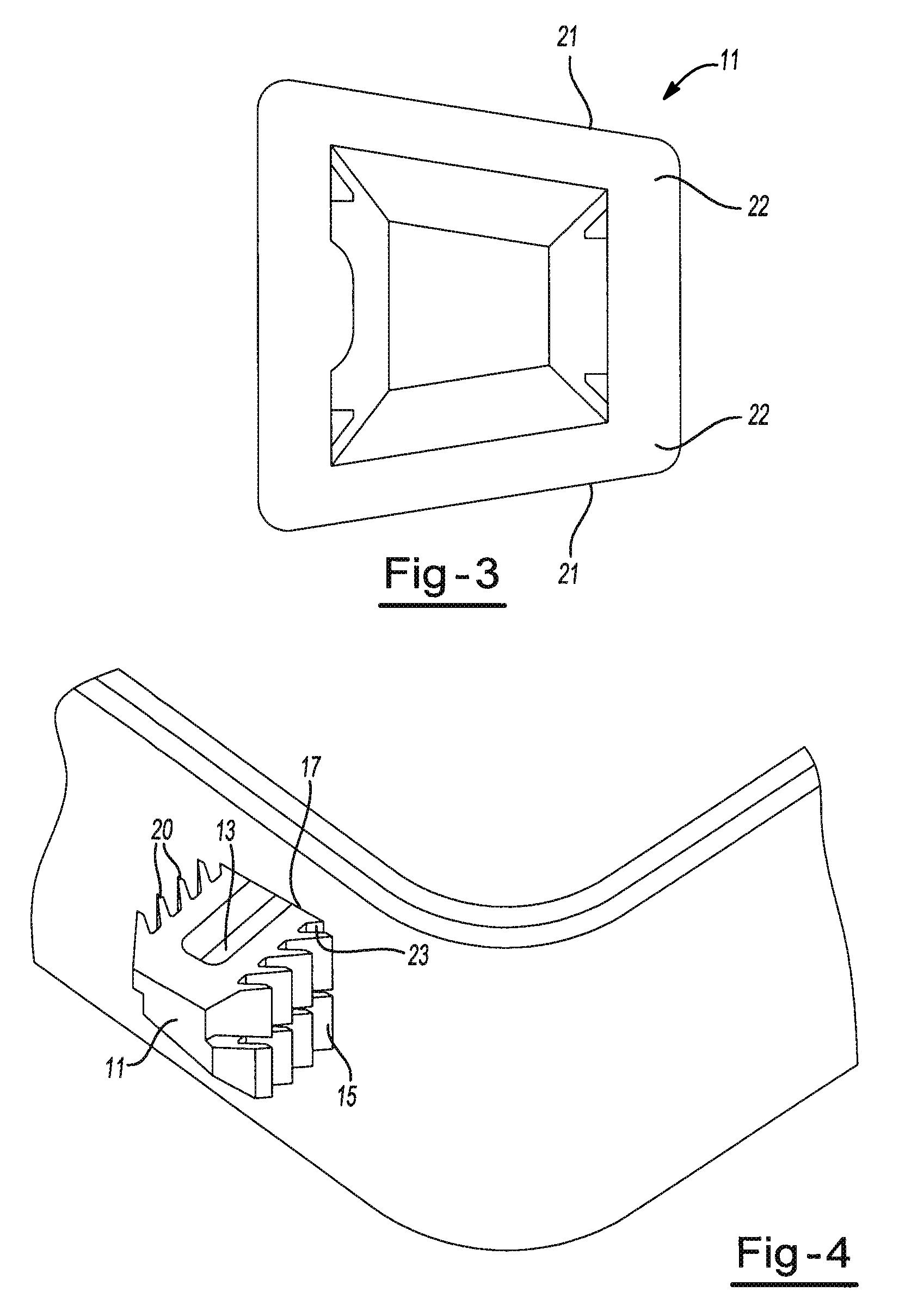
[0022]With reference to FIGS. 1-3, there is illustrated an exemplary fastener 11 of the fastening system of the present invention. In the embodiment shown, the fastener 11 includes a cap surface 12, a shank portion 13, four side walls 14 defining the shank portion 13 and six flexible wings 15 extending from two of the four side walls. However, it is contemplated that the fastener may include fewer or greater than four side walls and fewer or greater than 6 flexible wings extending along the side walls of the shank portion and that the flexible wings may be located on all or less than all of the side walls.

[0023]The cap surface 12 is shown as being substantially flat and of larger surface area than any remaining cross section of the shank portion. However, the cap surface may also be conical, triangular, or any other non-flat shape so long as the area of the cap is large enough to prevent slippage of the cap through a corresponding aperture. The cap surface may be separate from or in...


PUM

PropertyMeasurementUnit
heightaaaaaaaaaa
heightaaaaaaaaaa
heightaaaaaaaaaa

Abstract

A fastening system and method of use is disclosed. The fastening system includes a substrate, an aperture and a fastener. The fastener includes flexible wings that allow for insertion of the fastener into an aperture of a vehicle component.

Description

CLAIM OF PRIORITY[0001]The present application claims the benefit of the filing date of U.S. Provisional Application Ser. No. 61 / 083,355 filed Jul. 24, 2008 and the entirety of the contents of this application being hereby expressly incorporated by reference.FIELD OF THE INVENTION[0002]The present invention is directed toward a fastening system, and more particularly, to a fastening system employing a fastener of the type generally referred to as a “push-pin” or “christmas-tree” fastener.BACKGROUND OF THE INVENTION[0003]Push-pin and christmas-tree fasteners are well known within the art. These fasteners are designed for secure fit and difficult removal while at the same time allowing for easy insertion.[0004]A particular challenge in using these types of fasteners, especially in the automotive field, lies in providing a fastener that will afford the most secure attachment in combination with the simplest insertion process and fewest additional parts or insertion steps. Often, improp...

Claims


Application Information

Patent Timeline
Patent Type & Authority Applications(United States)
IPC IPC(8): F16B19/00
CPCF16B19/004F16B21/084Y10T29/49947Y10T29/49959Y10T24/303Y10T24/309Y10T29/49952
Inventor NITSCHE, OLAF
Owner ZEPHYROS INC
Why Eureka
Try Eureka