Fuel system for multi-fuel engine

a fuel system and engine technology, applied in the direction of electrical control, process and machine control, etc., can solve the problems of increasing the reducing the fuel reducing the efficiency of the engine, so as to facilitate the separation of fuel and reduce the cost and complexity of the fuel system. , the effect of reducing the cost and complexity of the fuel system

Inactive Publication Date: 2010-02-04
FORD GLOBAL TECH LLC
View PDF37 Cites 26 Cited by
  • Summary
  • Abstract
  • Description
  • Claims
  • Application Information

AI Technical Summary

Benefits of technology

[0006]In this way, at a first operating condition (e.g. at lower engine outputs) a fuel pump may be operated to provide a fuel mixture to the fuel separator at a suitable pressure for facilitating fuel separation; while at a second operating condition (e.g. at higher engine outputs), the same fuel pump may be operated to provide a fuel having a higher heat of vaporization to the engine. This higher heat of vaporization fuel may have been previously separated from the fuel mixture during a previous lower output operation of the engine. This approach enables the fuel system to perform multiple functions with the same fuel pump, thereby enabling a reduction in cost and complexity of the fuel system, as well as improving fuel efficiency of the engine.

Problems solved by technology

However, the inventors herein have recognized a disadvantage with this approach.
For example, even though the fuel pump may be operated to enable or improve the fuel separation process, this additional fuel pump may reduce fuel efficiency of the engine, increase the complexity of the fuel system, and increase the cost of the fuel system.

Method used


Image

  • Fuel system for multi-fuel engine
  • Fuel system for multi-fuel engine
  • Fuel system for multi-fuel engine

Examples


Embodiment Construction

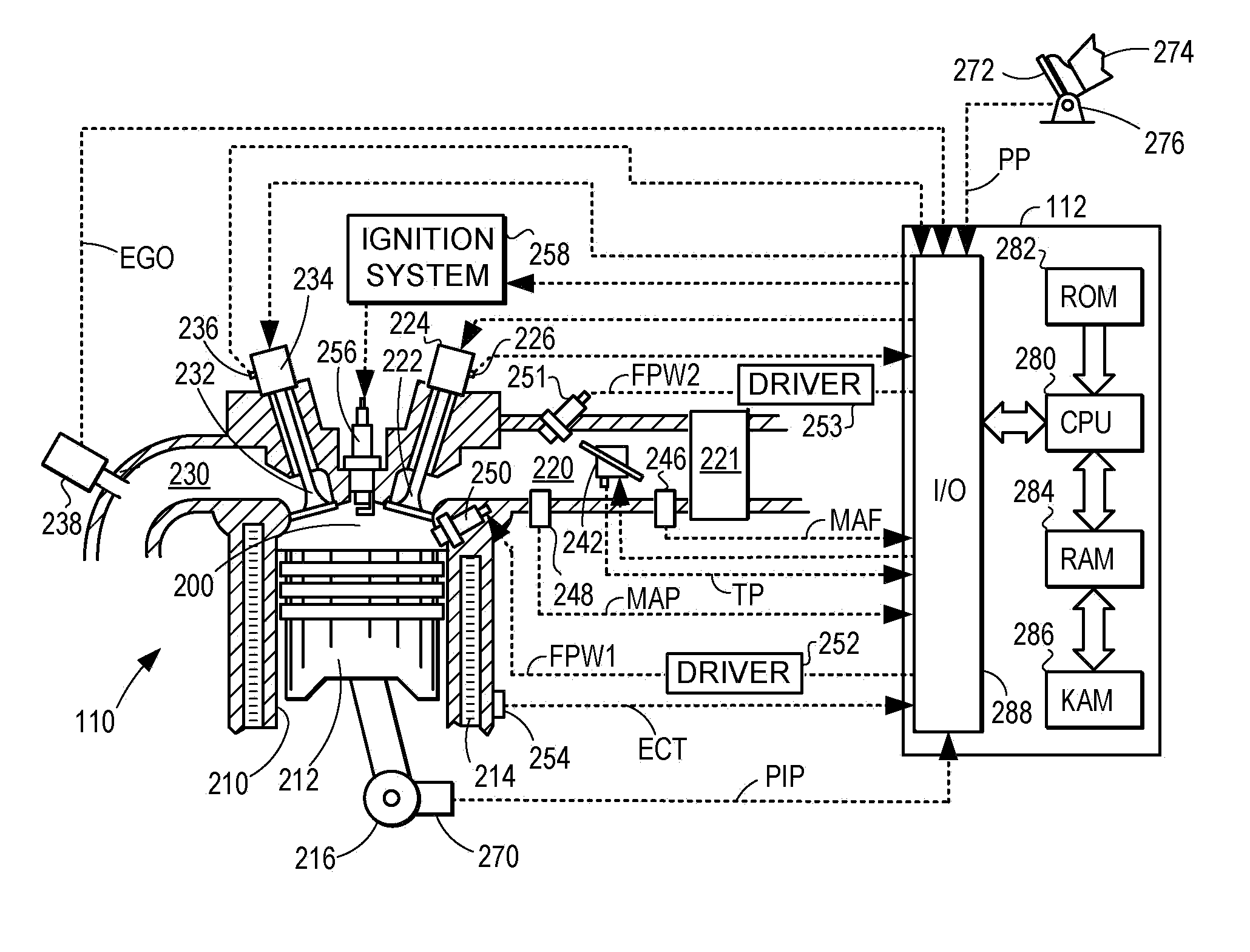
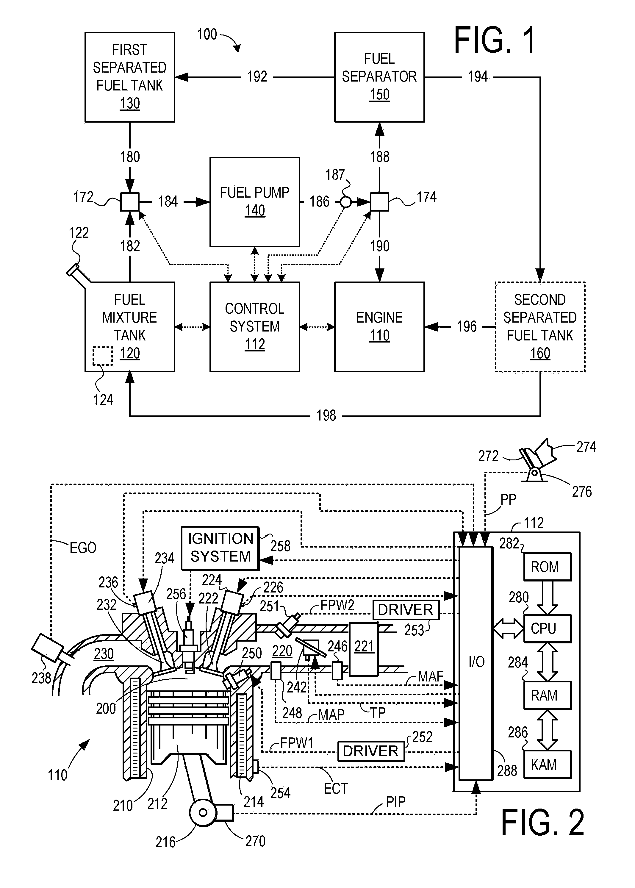
[0013]FIG. 1 illustrates an example fuel system 100 for a fuel burning engine 110. As a non-limiting example, fuel burning engine 110 may refer to an internal combustion engine for a vehicle and may include one or more combustion chambers or cylinders. An example cylinder of engine 110 is described in greater detail with reference to FIG. 2.

[0014]As described herein, fuel system 100 may be selectively operated to deliver a first fuel having a higher heat of vaporization (e.g. an alcohol rich fuel) to the engine via one or more direct fuel injectors forming a first injector group and a second fuel having a lower heat of vaporization (e.g. a gasoline rich fuel) may be delivered to the engine via one or more port fuel injectors forming a second injector group. The alcohol rich fuel as described herein refers to a fuel that includes a higher concentration of alcohol than the gasoline rich fuel. Conversely, the gasoline rich fuel as described herein refers to a fuel that includes a highe...


PUM


Abstract

A fuel system and a method of operation of the fuel system are described in the context of a multi-fuel internal combustion engine. As a non-limiting example, the method includes: varying a composition of fuel supplied to an inlet of a fuel pump responsive to engine output; operating the fuel pump to provide pressurized fuel at an outlet of the fuel pump using the fuel received at the inlet of the fuel pump; supplying the pressurized fuel from the outlet of the fuel pump to the internal combustion engine and to a fuel separator; and varying a proportion of the pressurized fuel supplied to the internal combustion engine relative to the fuel separator responsive to the engine output.

Description

BACKGROUND AND SUMMARY[0001]Fuel burning engines, such as internal combustion engines, may receive fuel via a fuel system. Some fuel systems may deliver fuel to the engine via port fuel injectors, whereby fuel is injected into an intake port of the engine. Other fuel systems may deliver fuel to the engine via direct fuel injectors, whereby fuel is injected directly into the cylinders of the engine.[0002]Other fuel systems have been proposed that include both port fuel injectors and direct fuel injectors. For example, the papers titled “Calculations of Knock Suppression in Highly Turbocharged Gasoline / Ethanol Engines Using Direct Ethanol Injection” and “Direct Injection Ethanol Boosted Gasoline Engine: Biofuel Leveraging for Cost Effective Reduction of Oil Dependence and CO2 Emissions” by Heywood et al. are one example. The Heywood et al. papers describe directly injecting ethanol via direct fuel injectors in order to improve charge cooling effects, while also relying on port injecte...

Claims


Application Information

Patent Timeline
Patent Type & Authority Applications(United States)
IPC IPC(8): F02M43/04F02M37/22F02D41/30
CPCF02B2075/125F02D19/084F02D13/0215F02D13/0253F02D19/0605F02D41/0025F02D2200/0612F02M37/0064F02M37/0088Y02T10/36Y02T10/123F02D19/0665F02D19/0671F02D19/0676F02D19/0692F02D19/081F02B2275/16Y02T10/12Y02T10/30
Inventor LEWIS, DONALD J.LEONE, THOMAS G.
Owner FORD GLOBAL TECH LLC
Why Eureka
Try Eureka