Static Compression Device

a compression device and compression tube technology, applied in the field of static compression devices, can solve the problems of significantly increasing patient morbidity, significantly reducing fusion rate, and many problems, and achieve the effect of more control over the for

Inactive Publication Date: 2010-04-01
IB MEDICAL
View PDF12 Cites 28 Cited by
  • Summary
  • Abstract
  • Description
  • Claims
  • Application Information

AI Technical Summary

Benefits of technology

[0009]The Static Compression Device (SC device) of the present invention allows for active, measurable compression of a fusion graft by the surgeon at the time of surgery. The SC device is attachable to adjacent vertebral bodies or other pieces of bone and has a device that applies compressive force to the adjacent vertebral bodies or other pieces of bone to assist fusion according to Wolff's law. The SC device has a locking mechanism that maintains the compression applied at surgery, but prevents further compression (settling) from occurring after surgery. So, the SC device allows the surgeon th

Problems solved by technology

However, several problems remain.
Additionally, using autograft bone typically involves the use of a second incision, which significantly increases patient morbidity.
Allograft bone (bone from another human) is a viable option, but has considerably lower fusion rates than autograft and is generally not considered a good choice in multiple level fusion surgery.
However, this has not been found to be the case.
In addition,

Method used


Image

  • Static Compression Device
  • Static Compression Device
  • Static Compression Device

Examples


Embodiment Construction

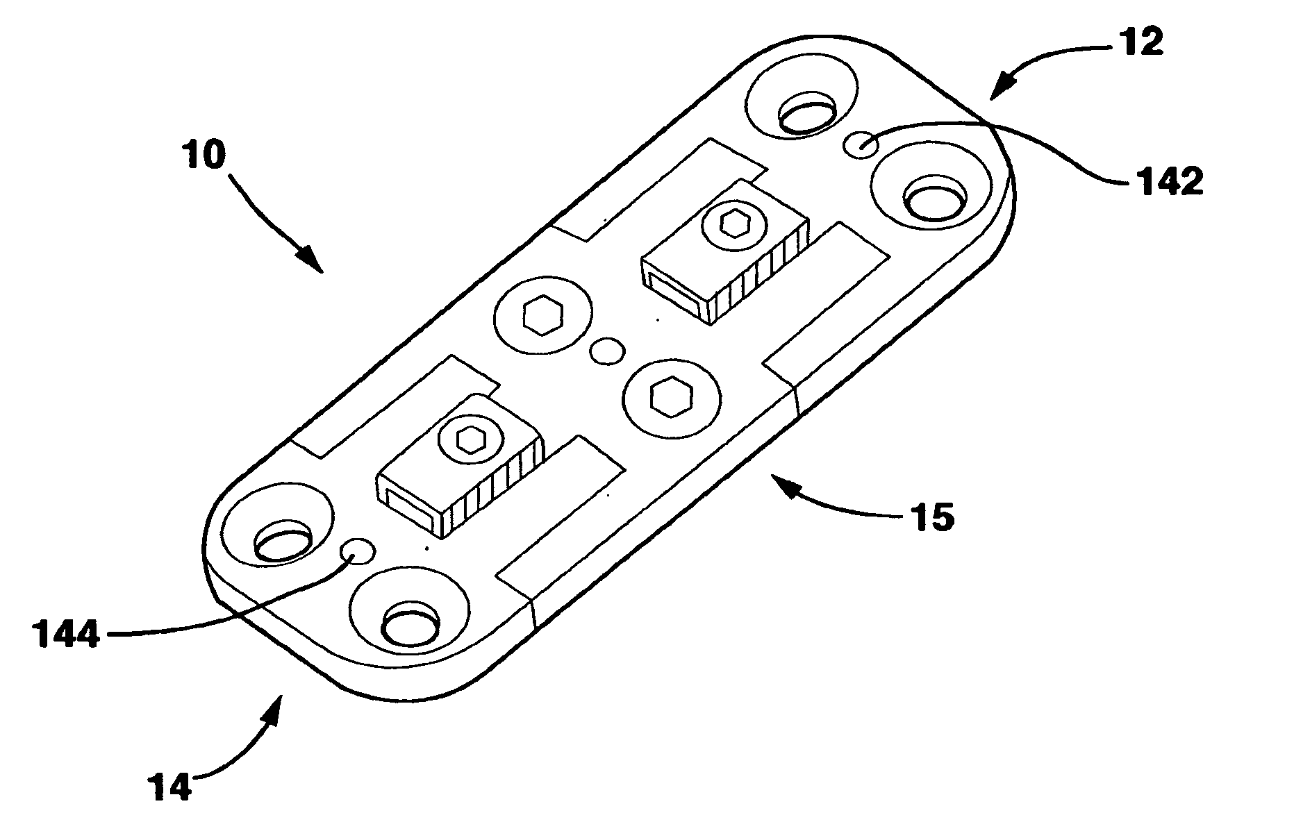
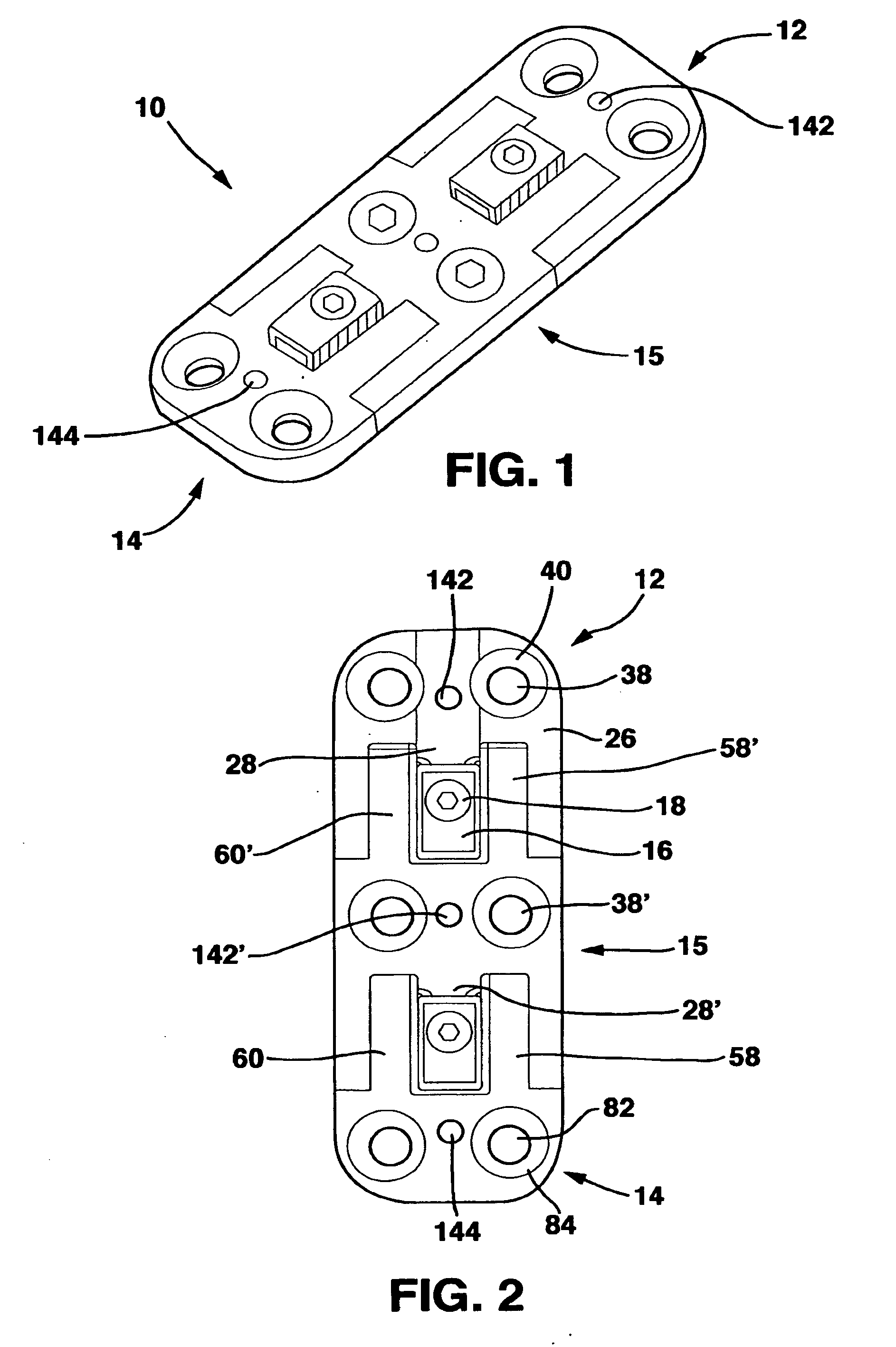
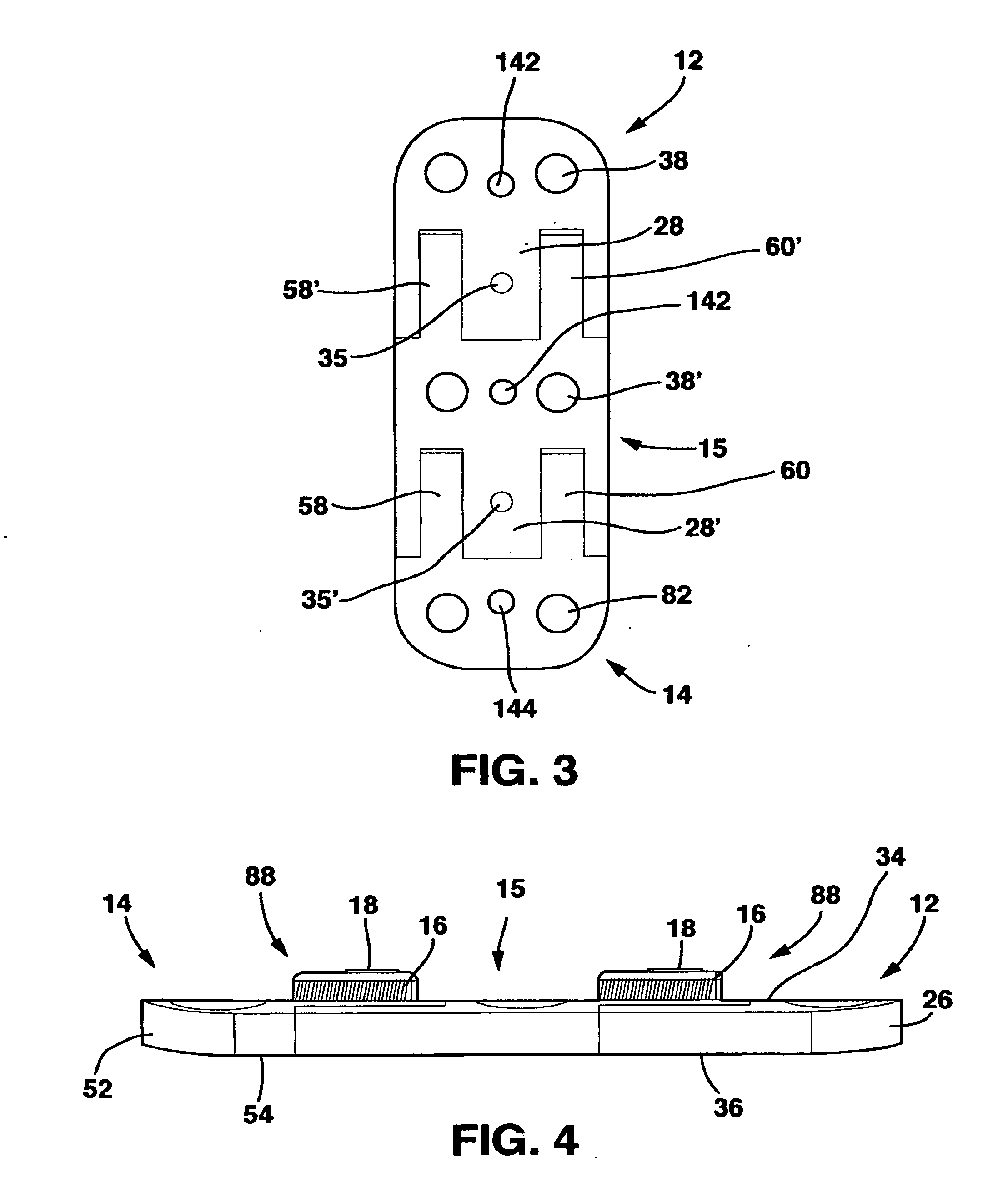
[0076]The SC device 10 in a preferred embodiment shown in FIGS. 1-14 and 18 has five main parts, a male plate 12, a female plate 14, an interconnecting plate 15, a locking clamp 16 and a locking screw 18 that, in combination with standard cancellous bone screws (not shown) fix the SC device 10 to the patient's vertebrae. The SC device 10 has a top side 20, a bottom side 22 and opposed medial sides 24.

[0077]The male plate 12 has a male main body 26 and a central protrusion 28 extending away from the male main body 26. The central protrusion 28 has a top surface 30, a longitudinal axis 32, a bottom surface 33 and parallel sides 36. Central protrusion 28 also has a threaded hole 35 in the top surface 30.

[0078]The male plate 12 also has a pair of side protrusions 29 extending away from the male main body 26 on opposite sides of the central protrusion 28. Each of the side protrusions 29 has an inner surface 37 and an outer surface 39. The inner surfaces 37 are directed toward the central...


PUM


Abstract

A Static Compression Device (SC device) for active, measurable compression of a fusion graft by the surgeon at the time of surgery is disclosed. The SC device is attachable to adjacent vertebral bodies or other pieces of bone and has a device that applies compressive force to the adjacent vertebral bodies or pieces of bone to assist fusion according to Wolffs law. The SC device has a locking mechanism that maintains the compression applied at surgery, but prevents further compression (settling) from occurring after surgery. The SC device allows the surgeon the ability to compress a segment, measure the applied compression, and lock the segment in the compressed position. In one embodiment of the invention, the pressure is applied to the SC device through a compression device that applies a desired and measurable amount of force. In this embodiment, the combination of the SC device with a pressure applying and measuring device allows the surgeon more control over the force applied to a cervical, thoracic or lumbar implant than has previously been available. In the preferred embodiment, the SC device compresses two or more adjacent vertebrae across an adjacent bone graft to facilitate fusion of these vertebrae to treat pain produced by pressure from the disks between such vertebrae bulging and resulting in contact with and pressure on the spinal cord and adjacent nerve roots. In other embodiments, the SC device may be used to apply measurable compression across any type of bony interface (e.g. fractures) to facilitate union.

Description

BACKGROUND OF THE INVENTION[0001]1. Field of the Invention[0002]The present invention is directed to devices and methods to compress two or more adjacent vertebrae across an adjacent bone graft to facilitate fusion of these vertebrae to treat pain produced by pressure from the disks between such vertebrae bulging and resulting in contact with and pressure on the spinal cord and adjacent nerve roots[0003]2. Description of Related Art[0004]For nearly half a century, anterior cervical discectomy and fusion has been performed for individuals complaining of intractable upper extremity pain due to cervical disc herniation or bone spurs at single or multiple levels. This procedure has undergone several significant modifications since its inception. The introduction of the Smith-Robinson technique of using tricortical iliac crest bone graft, the technique of denuding vertebral endplates of cartilage described by Zdeblick et al., and the present use of cervical plates have all represented si...

Claims


Application Information

Patent Timeline
IPC IPC(8): A61B17/80
CPCA61B17/7059A61B17/8004A61B17/8019A61B2019/464A61B17/8042A61B17/8023
Inventor IBRAHIM, ZAKI G.BERTELE, THEODORE P.
Owner IB MEDICAL
Why Eureka
Try Eureka