Device for blow-molding containers

a technology for blow-molding containers and containers, applied in the field of blow-molding containers, can solve the problems of increasing the overall amount of wear, affecting maintenance costs, and requiring devices for taking up space, and achieve the effect of prolonging the li

Active Publication Date: 2012-07-12
SERAC GROUP
View PDF8 Cites 26 Cited by
  • Summary
  • Abstract
  • Description
  • Claims
  • Application Information

AI Technical Summary

Benefits of technology

[0007]An object of the invention is to provide a de...

Problems solved by technology

Nevertheless, the forces contribute to premature wear of the hinges of the movable portions of the molds and of the holding mechanisms, which wear makes it necessary to provide devices for taking up slack.
The overall amount of wear is increased by the means for hol...

Method used


Image

  • Device for blow-molding containers
  • Device for blow-molding containers
  • Device for blow-molding containers

Examples


Embodiment Construction

[0031]The device for blow-molding containers in this example is for fabricating bottles with threaded necks. The bottles are fabricated from preforms that are inserted into molds prior to air being blown into the insides of the preforms in order to inflate them and form the bodies of bottles by pressing the preforms against the walls of the molds. The blow-molding method is itself known and is not described in greater detail herein.

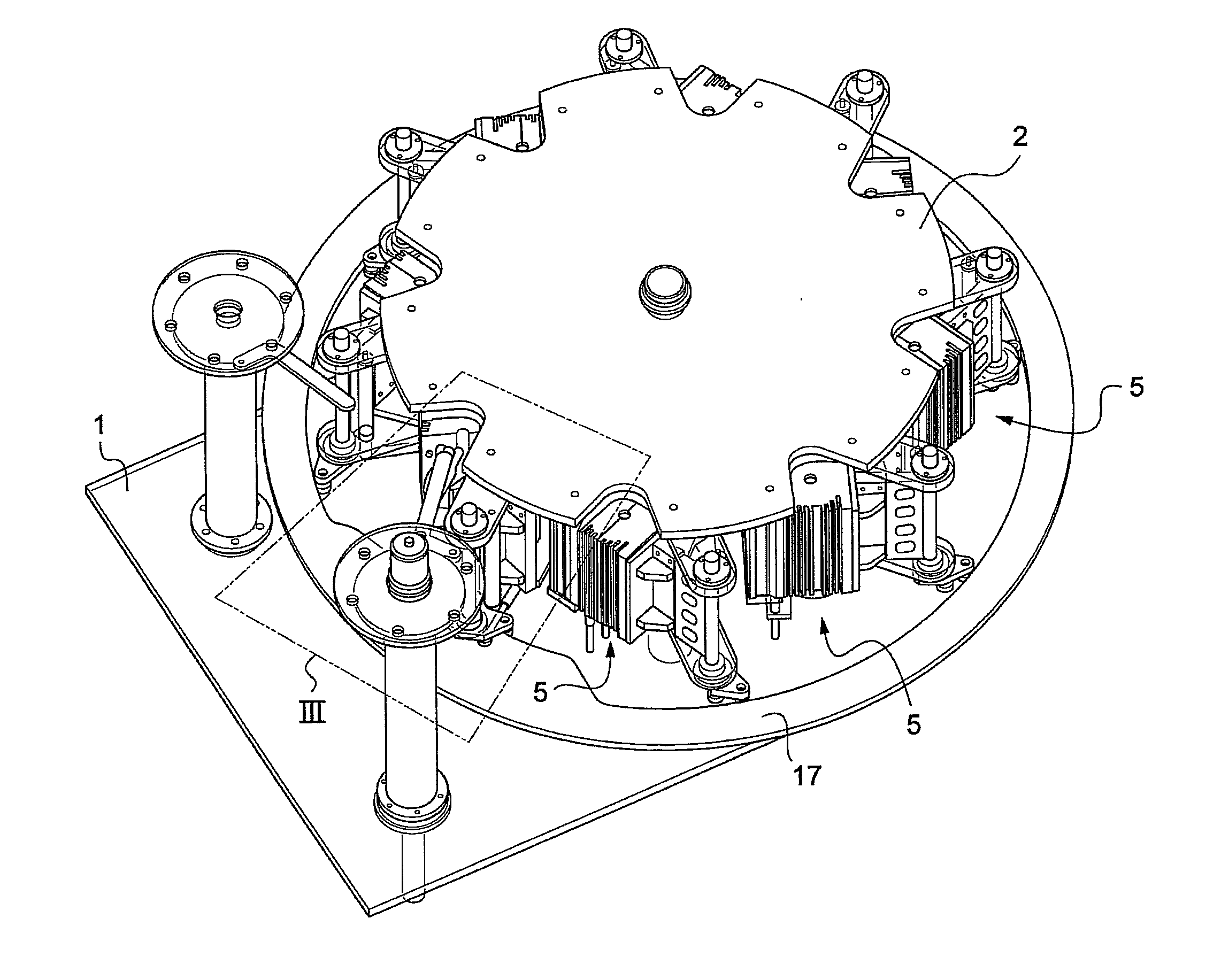
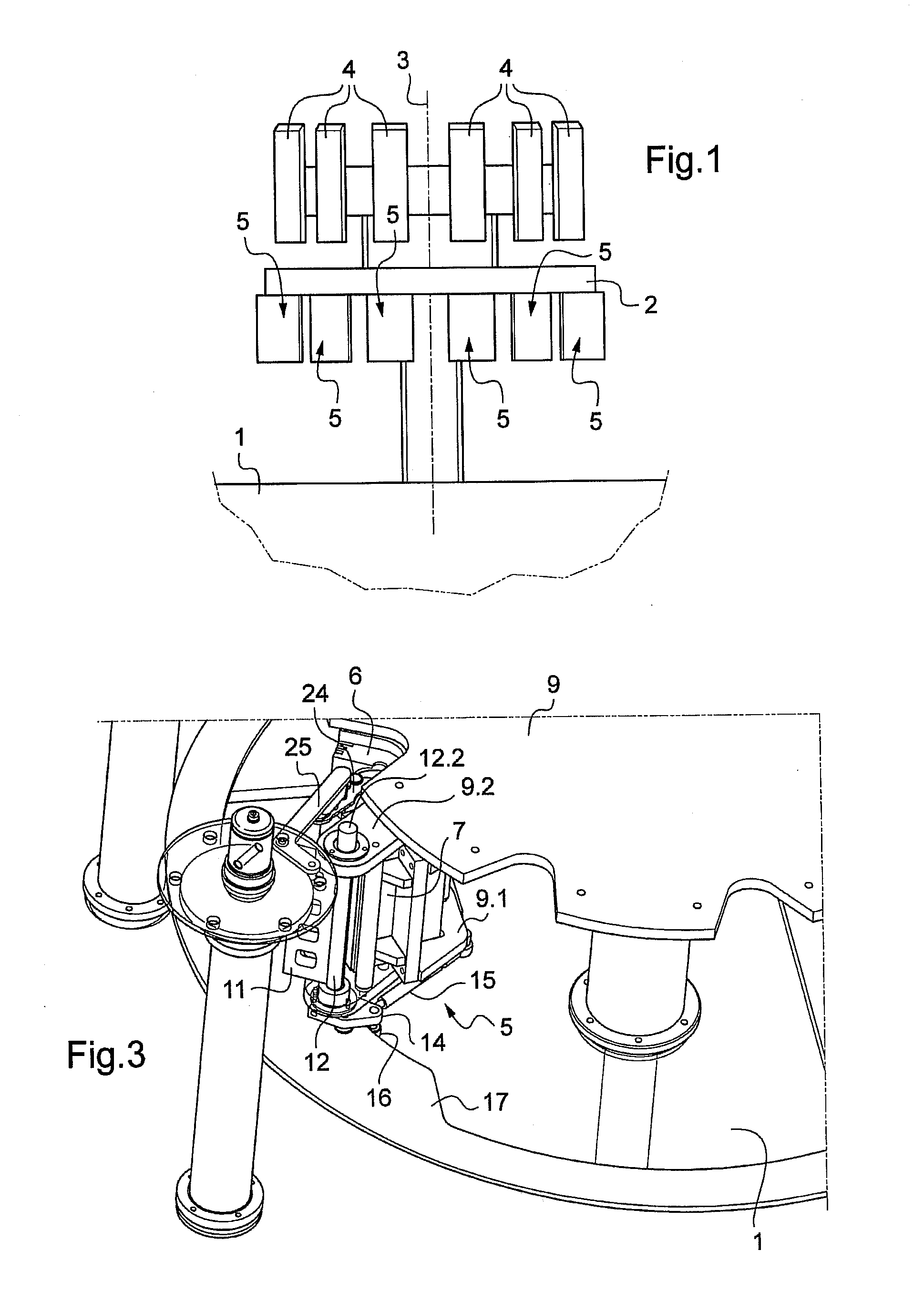
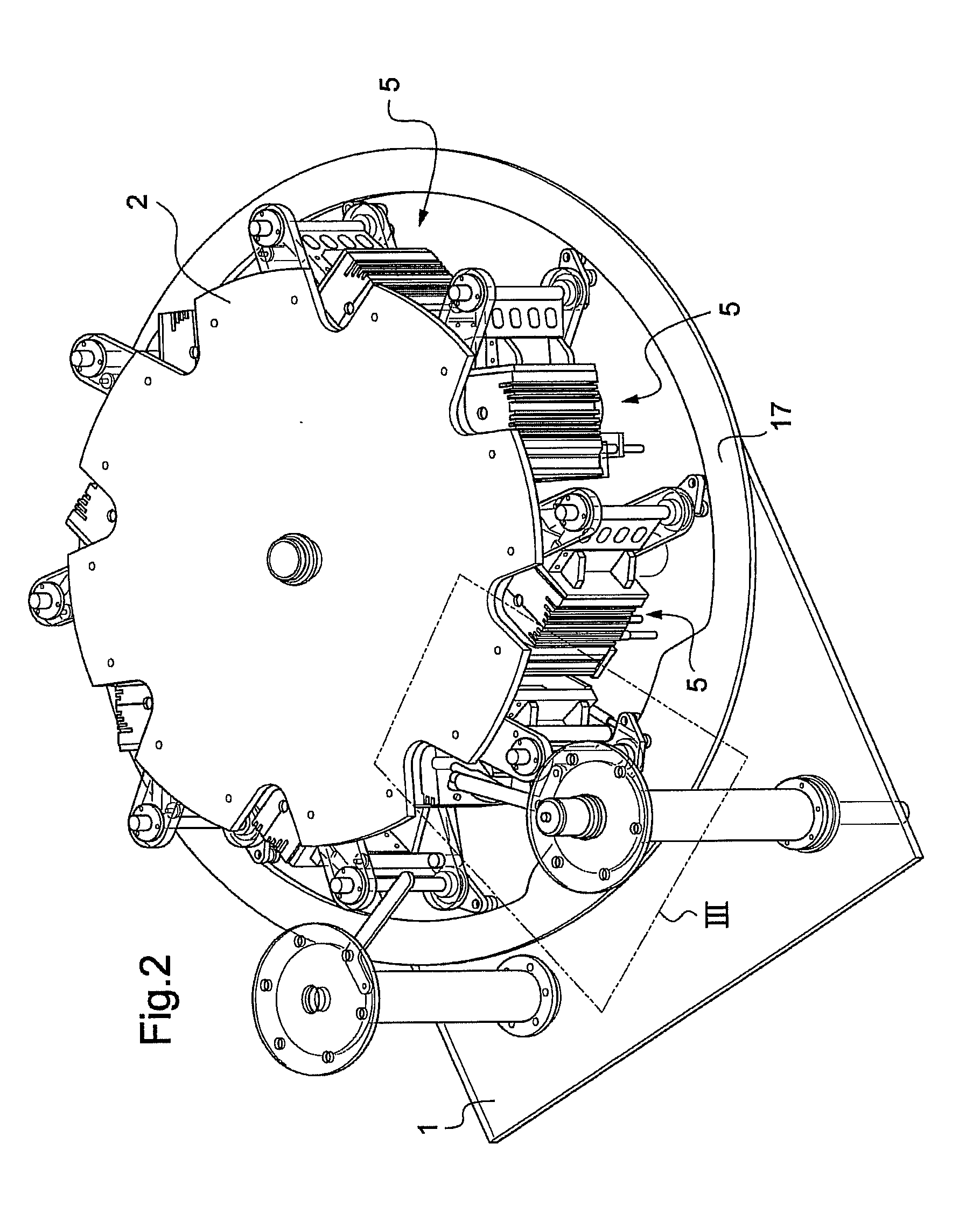
[0032]With reference to the figures, the device of the invention comprises a structure 1 and a platform 2 mounted to rotate on the structure 1 about an axis of rotation 3.

[0033]The platform 2 is provided with blower members 4 that are themselves known and with molds given overall reference 5 that are mounted beneath the blower members 4.

[0034]Each mold 5 comprises two mold portions, namely a stationary mold portion 6 and a movable mold portion 7 together with a bottom 8. Each mold portion 6, 7 includes a cavity corresponding to half of the outside shape o...


PUM

PropertyMeasurementUnit
Forceaaaaaaaaaa
Molding pressureaaaaaaaaaa
Heightaaaaaaaaaa

Abstract

A device for blow-molding containers, the device comprising a structure and a platform mounted to rotate on the structure about an axis of rotation, the platform being provided with blower members and with molds that are mounted under the blower members, each of which comprises a stationary mold portion and a movable mold portion that is movable by control means between an open position and a closed position for the mold, wherein the device includes blocking members for blocking the molds in the closed state, each blocking member comprising a strut mounted on the platform to move between a retracted position and a blocking position.

Description

FIELD OF THE INVENTION[0001]The present invention relates to a device for blow-molding containers. Such a device is generally designed to be installed in a line for producing packages that are intended in particular to contain liquids.BACKGROUND OF THE INVENTION[0002]A blow-molding device generally comprises a structure and a platform mounted to rotate on the structure about an axis of rotation. The platform is provided on its periphery with blower members and with molds mounted under the blower members. The device also includes control means for moving the molds between an open state and a closed state, a transporter for loading preforms into each of the molds, and a transporter for removing containers that have been blow-molded on the platform. Loading, blow-molding, and removal are performed in zones of the platform through which each mold passes in succession during the rotation of the platform. By way of example, the transporters comprise transfer stars and / or rectilinear trans...

Claims


Application Information

Patent Timeline
IPC IPC(8): B29C49/36
CPCB29C49/56B29C49/36B29C49/5602B29C49/5603B29C49/5608
Inventor GRAFFIN, ANDRE
Owner SERAC GROUP
Why Eureka
Try Eureka