Disposable couplings for biometric instruments

a biometric instrument and coupling technology, applied in the field of biometric measurement systems, can solve the problems of poor coupling between tissue and microscopic body, poor mechanical energy transmission between microscopic body and skin, and uneven surface of laser light, so as to facilitate transmission of energy, facilitate transmission of acoustic energy, and facilitate the effect of mechanical energy transmission

Inactive Publication Date: 2005-04-28
PAGE JOSEPH +1
View PDF10 Cites 62 Cited by
  • Summary
  • Abstract
  • Description
  • Claims
  • Application Information

AI Technical Summary

Benefits of technology

[0013] Photoacoustic measurement systems typically require a test site be energized with optical (photonic) energy and require sensing of returned mechanical (acoustic) energy. To effect such, electronic transducers including lasers and microphones must be interfaced with tissue. As made clear from the prior art, the physical interface may be embodied in many forms. In inventions taught herein, wearable systems which couple to a users' skin surface are of immediate concern. In particular, these systems include at least one laser and at least one microphone which are put into close proximity with a test subject's skin surface via coupling means.
[0014] Lasers and microphones may be included as parts of a system measurement head. Since a microphone which might include a relatively smooth surface is to be in communication with skin which is sometimes irregular and rough, a joint formed by the microphone and skin might not be conducive to efficient transmission of mechanical energy therebetween. In some cases, a medium such as a thick gel with appropriate density might be used to fill pores and spaces natural to skin surface and promote better transmission of acoustic energy into a microphone transducer. Carefully prepared gel materials facilitate transmission of energy to and from a tissue being tested.
[0015] Similarly, laser light tends to scatter from the irregular surface of the skin and is not well coupled to tissue lying just below the skin surface. Special geometries which may include special optical lenses, including possibly an immersion lens, may be used to encourage better transmission of laser light into tissue test sites.
[0016] Finally, where a measurement head is to be placed into contact with a test site, it is preferable that motion between the test site and detector head is minimized. An affixing means such as adhesive or mechanical grit helps to anchor a test head to a skin surface in a spatial coupling.
[0017] Laser and microphone devices tend to be expensive but are long-lasting and remain functional over a long lifetime. As such, they are preferably permanently affixed and mounted within an appropriate housing herein referred to as a ‘measurement head’. Conversely, materials such as gels, fluids, and lenses are sensitive to exposure and may have short lifetimes as a result of becoming dirty and otherwise contaminated. It is therefore desirable to separate these into cooperating subsystems whereby one is made disposable but renewable, and the other is permanent. Together the subsystems cooperate to form an improved comprehensive device with greater coupling efficiency and accordingly better system signal to noise ratio and ultimately higher performance.
[0018] A disposable element is prepared with optical coupling means, acoustic coupling means, and mechanical coupling means. The disposable element may be detached from a test head and replaced with a fresh and renewed disposable element from time-to-time as necessary. In this way, the lasers and microphones of a wearable in vivo photoacoustic effect measurement system are made efficiently coupled to tissue operable by users with special facility and equipment.

Problems solved by technology

Since a microphone which might include a relatively smooth surface is to be in communication with skin which is sometimes irregular and rough, a joint formed by the microphone and skin might not be conducive to efficient transmission of mechanical energy therebetween.
Similarly, laser light tends to scatter from the irregular surface of the skin and is not well coupled to tissue lying just below the skin surface.

Method used


Image

  • Disposable couplings for biometric instruments
  • Disposable couplings for biometric instruments
  • Disposable couplings for biometric instruments

Examples


Embodiment Construction

[0052] In accordance with each of preferred embodiments of these inventions, there is provided disposable coupling articles for use in conjunction with photoacoustic measurement systems. It will be appreciated that each of these embodiments described include an apparatus and that the apparatus of one preferred embodiment may be different than the apparatus of another embodiment.

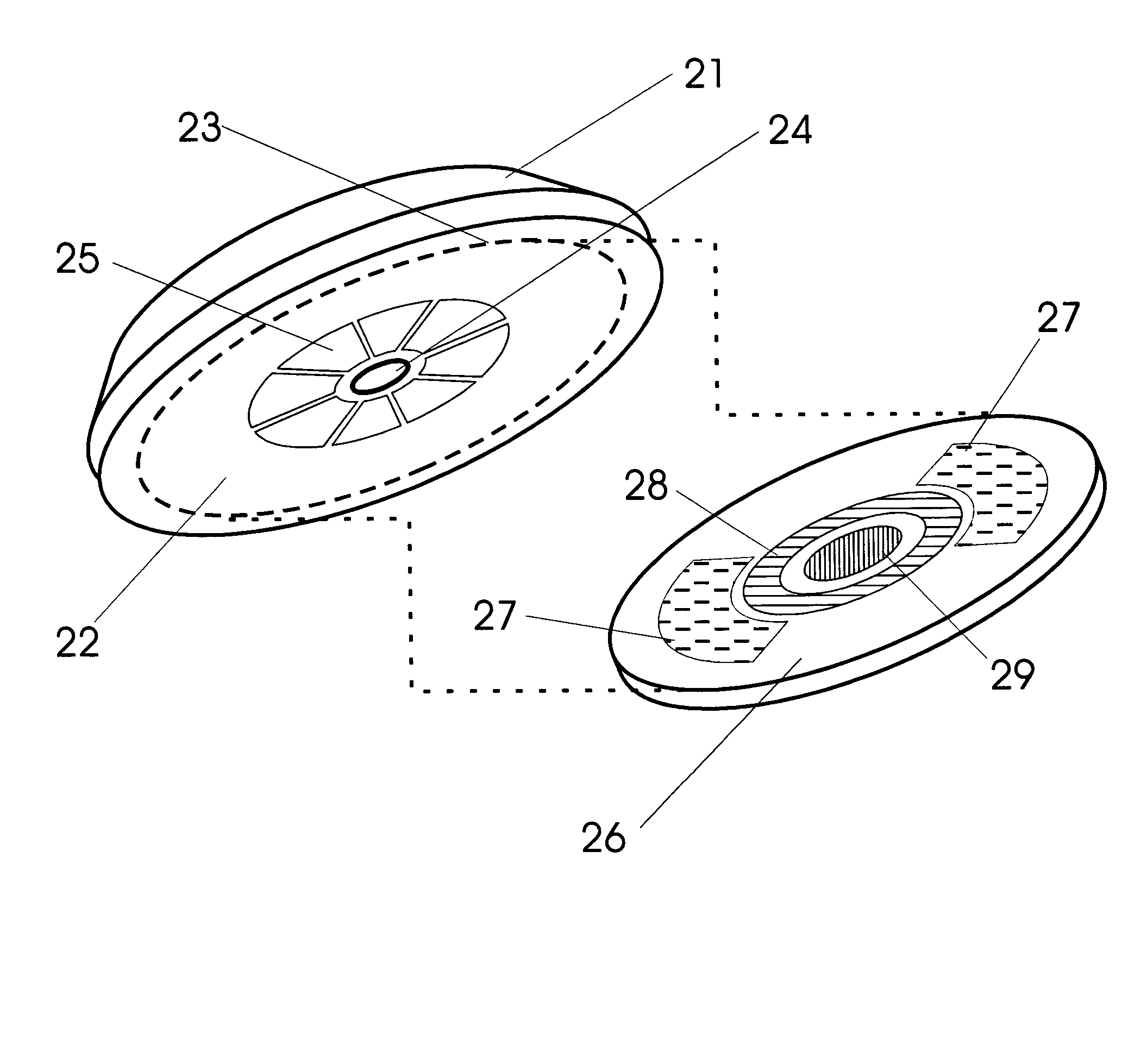
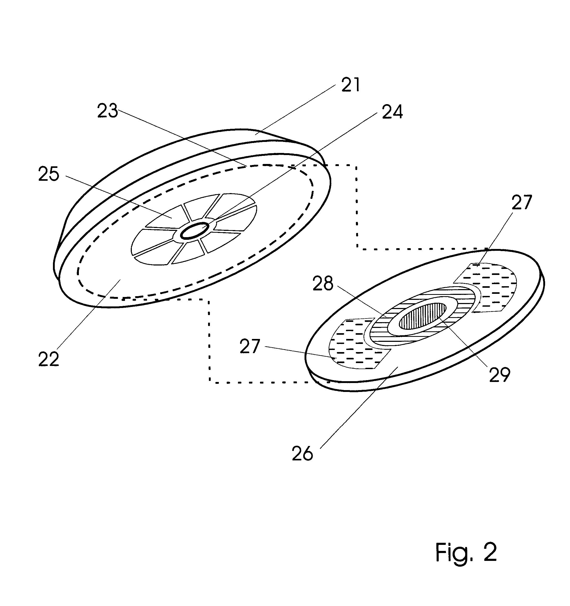
[0053] These inventions are primarily defined as disposable couplings in photoacoustic biometric measurement systems, the devices being formed of a thin substrate element having an optical coupling to efficiently pass optical energy from an optical source into human flesh and an acoustic coupling to efficiently pass acoustic energy to / from an acoustic transducer into human flesh.

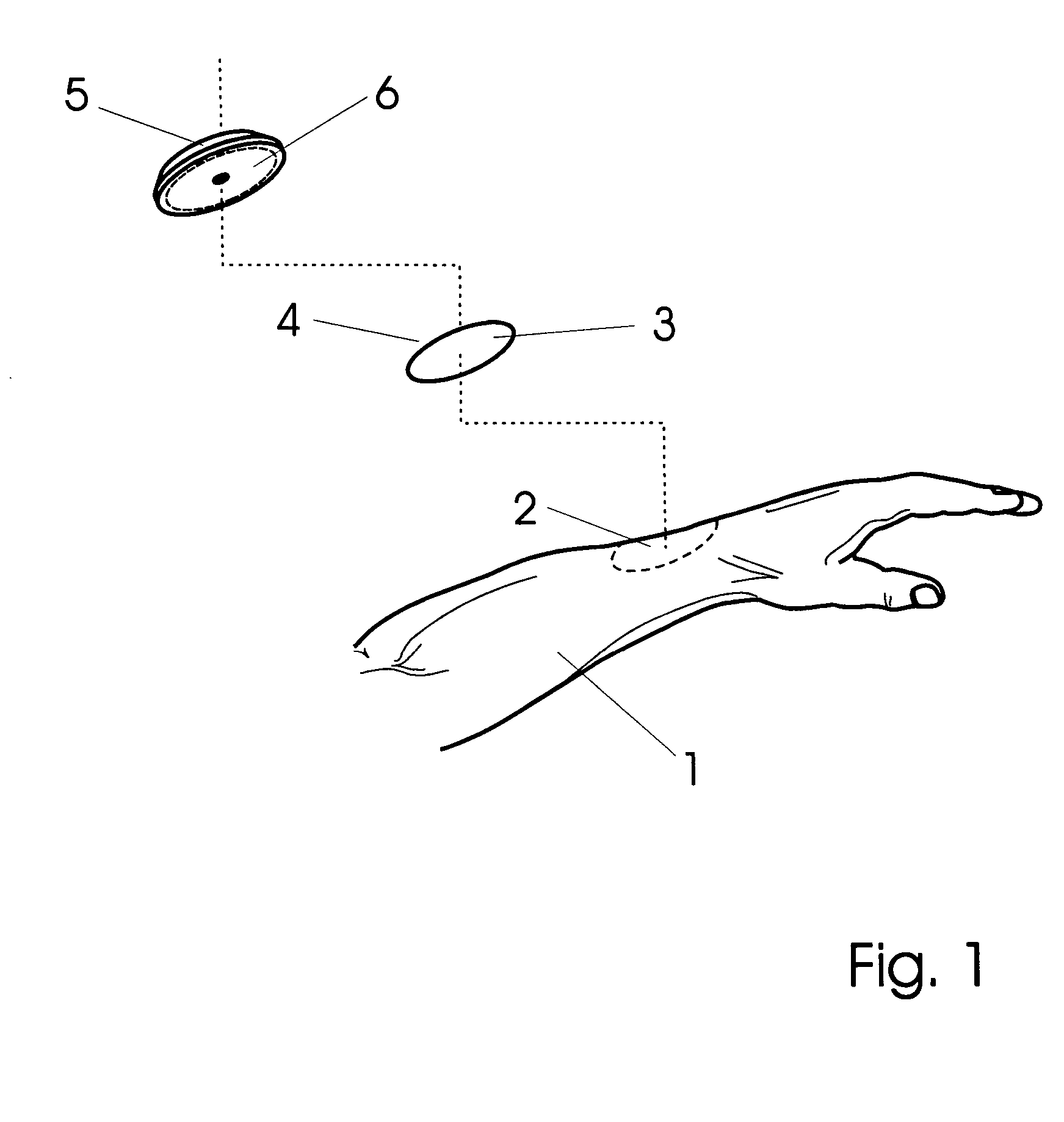
[0054] With reference to drawing FIG. 1, one can more fully appreciate the environment and use of preferred versions. A human subject 1 to be tested includes tissue at a test site 2 at the top side of the wrist where the skin is mod...


PUM


Abstract

Photoacoustic measurement system are configured with a special view towards efficient coupling of optical and acoustic energy between respective transducers and a tissue test site. In particular, a disposable substrate provides support for advanced optical paths including, for example, windows, lenses, and index matching gels or fluids. In addition, substrates may also accommodate arrays of coupling sites corresponding to a plurality of acoustic detectors spatially separated. These substrates may additionally include means to affix and secure the device to a measurement head having optoelectronic and electromechanical transducers therein. Further, these substrates include mechanisms which help to affix the substrates to test sites in stabile and secure fashion.

Description

BACKGROUND OF THE INVENTIONS [0001] 1. Field [0002] The following invention disclosure is generally concerned with biometric measurement systems employing a photoacoustic effect and specifically concerned with improved coupling between instruments and human tissue. [0003] 2. Prior Art [0004] Photoacoustic spectroscopy is a mature body of science. When applied to living beings, or in vivo photoacoustic spectroscopy, the technique involves coupling various transducers to live tissues. In these specialized systems, optical sources and acoustic detectors are placed in communication with various parts of the anatomy. This gives rise to a great plurality of coupling techniques each having associated benefits and faults. The following examples illustrate some important techniques used to join human tissues with electronic measurement systems. [0005] A first example of special coupling between a spectroscopic system and living human tissue relates to a principle call Attenuated Total Reflec...

Claims


Application Information

Patent Timeline
Patent Type & Authority Applications(United States)
IPC IPC(8): A61B5/00A61B7/04A61B8/00
CPCA61B5/0059A61B5/0095A61B8/4281A61B7/04A61B5/6833
Inventor PAGE, JOSEPHPLANTE, JAMES
Owner PAGE JOSEPH
Why Eureka
Try Eureka