Clip

a clip and clip technology, applied in the field of clips, can solve the problems of deterioration of the fitting capability of the clip b>101/b>, and achieve the effect of sufficient fitting capability

Active Publication Date: 2010-04-08
TOYOTA BOSHOKU KK
View PDF12 Cites 26 Cited by
  • Summary
  • Abstract
  • Description
  • Claims
  • Application Information

AI Technical Summary

Benefits of technology

[0006]It is an aspect of the present invention to provide a clip which has sufficient fitting capability with respect to a panel member even when the clip is provided with a wire insertion hole capable of holding a wire member.

Problems solved by technology

As the result, such a problem that fitting capability of the clip 101 is deteriorated has sometimes happened.

Method used


Image

  • Clip
  • Clip
  • Clip

Examples


Embodiment Construction

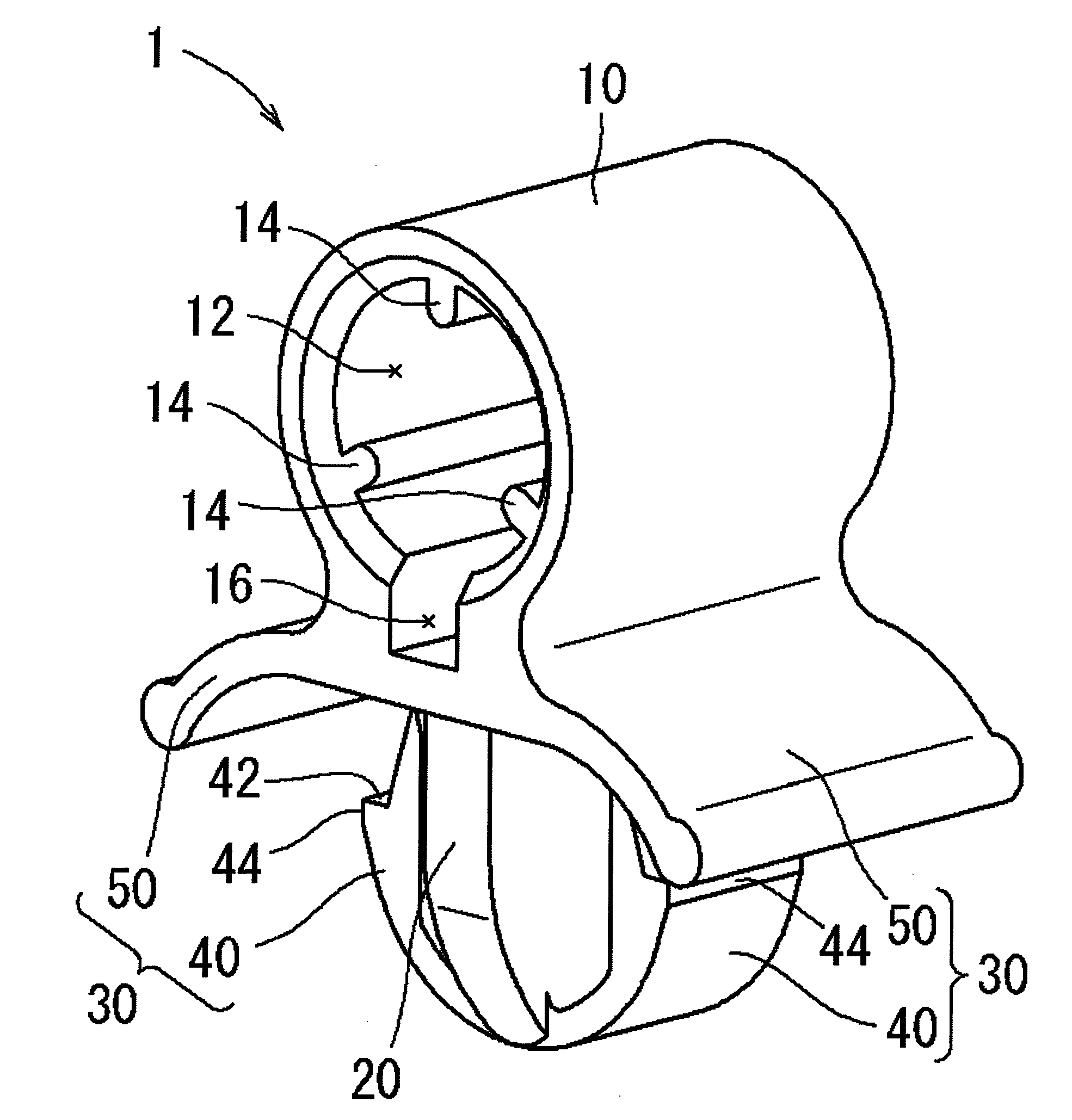
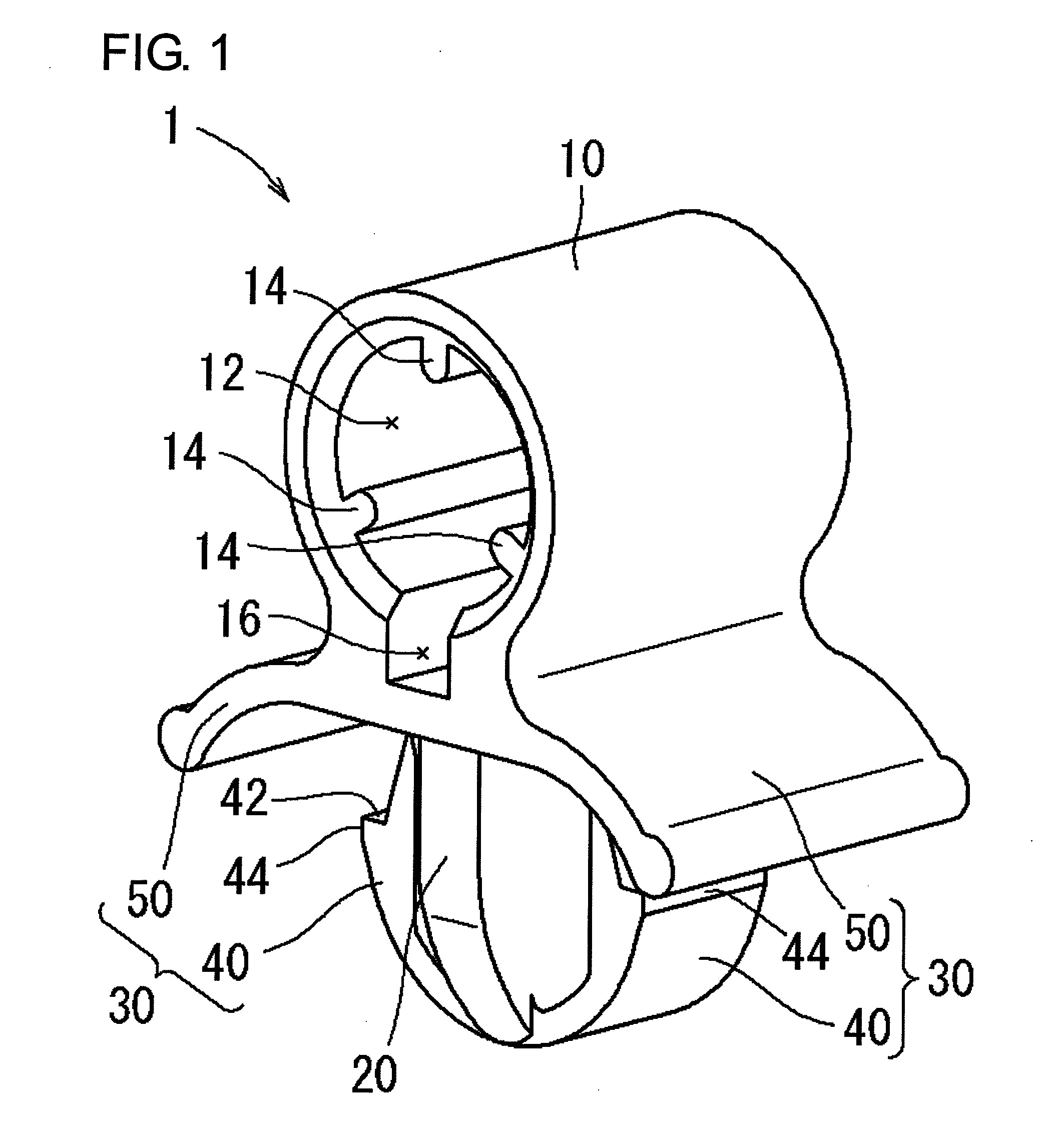
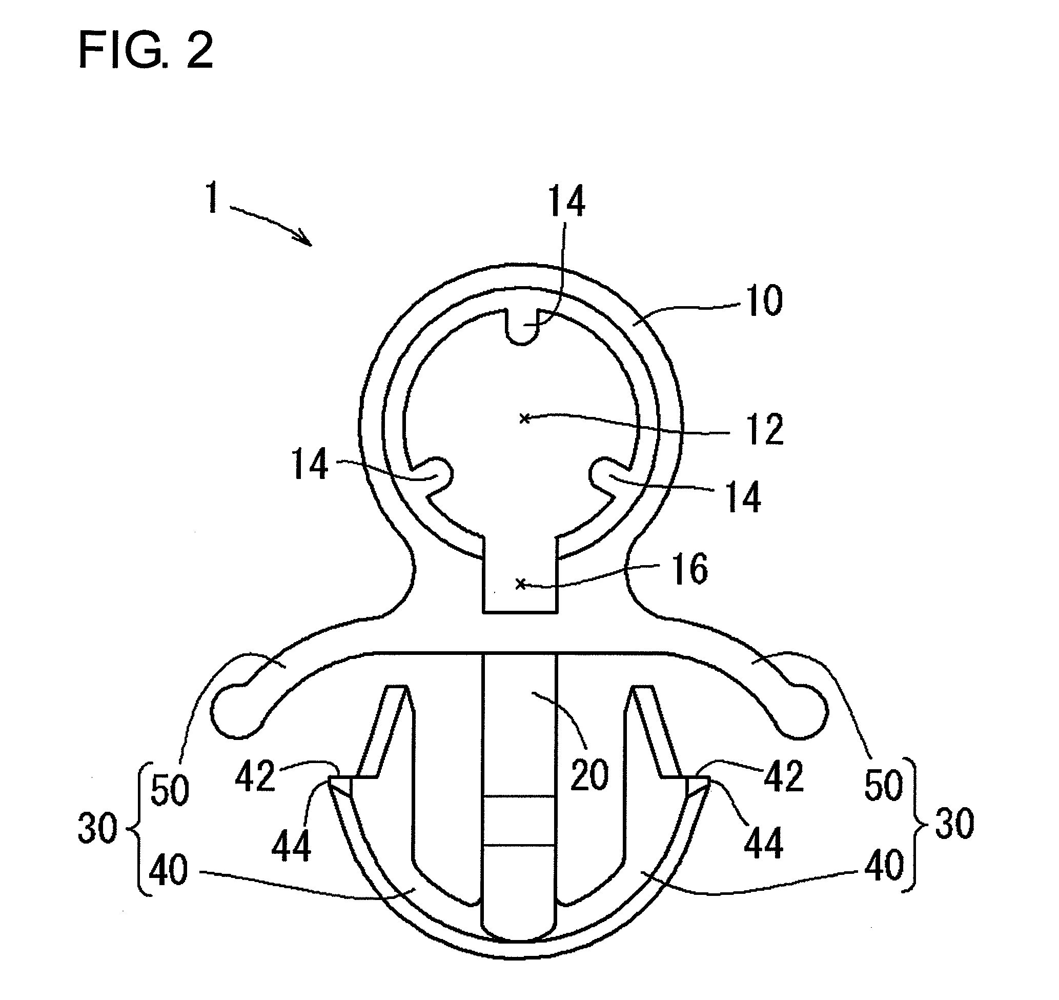
[0018]Exemplary embodiments of the present invention will be described with reference to FIGS. 1 to 7. FIG. 1 is a perspective view showing an entirety of a clip according to an exemplary embodiment of the present invention. FIG. 2 is a front view of the clip shown in FIG. 1. FIG. 3 is a right side view of the clip shown in FIG. 1. FIG. 4 is an explanatory view showing a state before the clip is fitted to a plate. FIG. 5 is an explanatory view showing a state while the clip is fitted to the plate. FIG. 6 is an explanatory view showing a state where the clip has been fitted to the plate. FIG. 7 is an explanatory view showing an example in which the clip is used.

[0019]Firstly, a clip 1 will be described with reference to FIGS. 1 to 3. As shown in these drawings, the clip 1 has a head part 10, a main part 20, and locking means 30. In the following description, these members 10, 20, 30 will be described separately.

[0020]The head part 10 is a part for holding a wire member (not shown in ...


PUM


Abstract

A clip for attaching a wire member to a panel member is provided. The clip includes a head part provided with a wire insertion hole capable of holding the wire member a main part supporting the head part and locking means for fitting the main part to a fitting hole of the panel member. The main part is a single body. An inside and an outside of the wire insertion hole are not communicated with each other in a radial direction thereof.

Description

BACKGROUND OF THE INVENTION[0001]1. Field of the Invention[0002]The present invention relates to a clip, and more particularly, to a clip for attaching a wire member to a panel member.[0003]2. Description of the Related Art[0004]U.S. Pat. No. 5,762,397 describes a clip for attaching a wire member to a panel member. In this art, as shown in FIG. 8, a clip 101 includes a head part 110 having a wire insertion hole 112 capable of holding a flexible spring (not shown) which is a wire member for supporting a pad of a seat back, a main part 120 for supporting this head part 110, and locking means 130 capable of fitting this main part 120 to a fitting hole in a plate which is a panel member (both of which are not shown). The flexible spring is passed through the wire insertion hole 112 through a slit 122 which is formed in the main part 120 to be held in a clamped manner. In a state where the flexible spring is thus held, the main part 120 can be fitted to the plate with the locking means 1...

Claims


Application Information

Patent Timeline
Patent Type & Authority Applications(United States)
IPC IPC(8): F16L3/12
CPCF16L3/127B60N2/682B60N2/72
Inventor OHNO, TATSUYA
Owner TOYOTA BOSHOKU KK
Why Eureka
Try Eureka