Method for fan control according to the position of a device and device implementing the procedure

Active Publication Date: 2010-05-06
INTERDIGITAL CE PATENT HLDG
View PDF6 Cites 4 Cited by
  • Summary
  • Abstract
  • Description
  • Claims
  • Application Information

AI Technical Summary

Benefits of technology

[0016]According to an improvement, the fan is placed on the side at the bottom of the device in a vertical position, and blows the external air into the device. In this way, the maximum noise generated by the air flow is located inside the device and n

Problems solved by technology

In this way, the user is informed of a malfunction of

Method used


Image

  • Method for fan control according to the position of a device and device implementing the procedure
  • Method for fan control according to the position of a device and device implementing the procedure
  • Method for fan control according to the position of a device and device implementing the procedure

Examples


Embodiment Construction

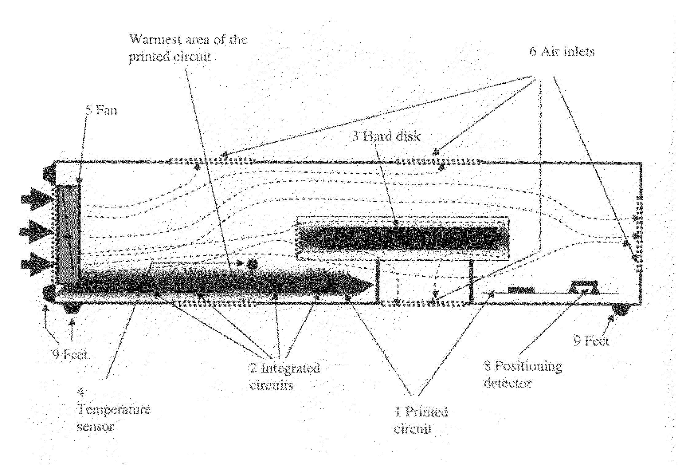
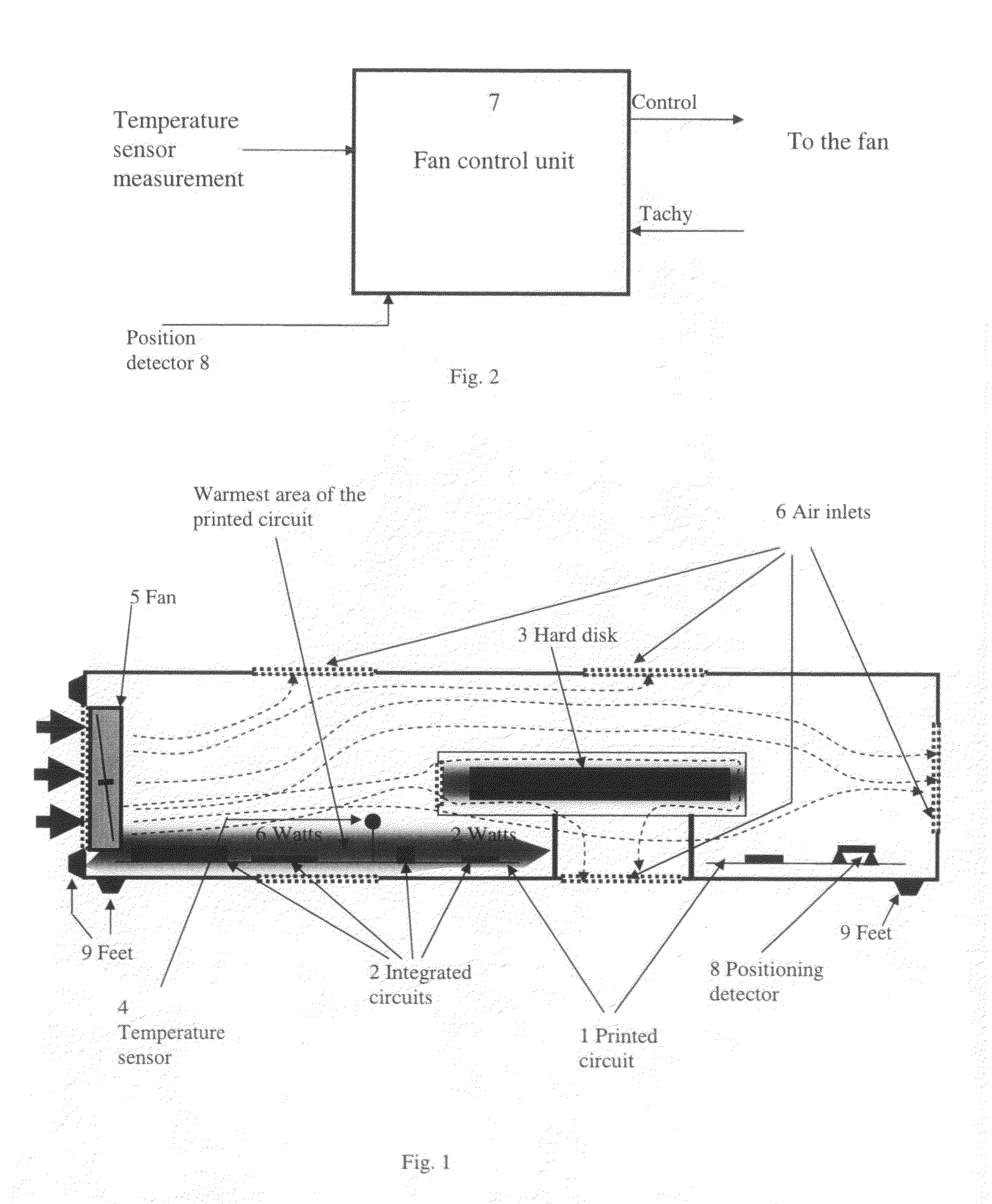
[0022]FIG. 1 describes a section of an electronic device, a television decoder for example. The device comprises a printed circuit 1 on which the electronic circuits 2 are arranged. A hard disk 3 enables recording of data, particularly of lengthy audiovisual works. The circuits 2 and the disk 3 consume a lot of power and emanate heat, for example, for a television decoder dissipating 17 Watts, its central processing unit releases itself a heat level of approximately 3 Watts. As a result, certain zones of the decoder, marked in grey on FIG. 1, are warmer than others. A temperature sensor 4 located within one of these hot areas, preferably close to the circuit which produces the most heat, provides a voltage proportional to the temperature. A fan 5 provides cool air from the exterior and transfers it to the decoder cavity via an opening realized on the left side of the device. Several air inlets 6 cut in the decoder box allow the outlet of the hot air, from the underside, the right si...


PUM


Abstract

The present invention relates to a control method for the operation of a fan equipping an electronic device. A determination step detects the vertical or horizontal position of the electronic device. The fan is not started up during the powering up of the device while the device is in a vertical position. The flow of air produced by the “fireplace” effect in the device in a vertical position suffices to ensure correct ventilation. According to an improvement the device has a sensor measuring the internal temperature of the device, whatever the position of the device, the fan being started up from a determined temperature. The present invention relates also to a device implementing the method.

Description

FIELD OF THE INVENTION[0001]The present invention relates to a control method for a fan according to the horizontal or vertical position of a device. The present invention relates also to a device which implements the method.BACKGROUND[0002]Electronic devices consume a great deal of energy during normal operation. This energy is transformed into heat that is concentrated within devices that are generally sealed. With the concentration of integrated circuits, the electronics of a modern device release more heat per unit of surface than older devices. This concentration leads to a temperature increase which is eventually prejudicial to the reliability of the integrated circuits and other sensitive elements such as central processing units or the hard disk. To resolve this problem, a cooling system is implemented into the electronic devices using one or several fans which blow cool air from the exterior in order to cool the interior. The integration of a hard disk into television decod...

Claims


Application Information

Patent Timeline
IPC IPC(8): F04D15/00F01B27/00
CPCG05D23/1909G06F1/20H04N5/64H04N5/76
Inventor GUITTON, XAVIERAUBIN, ANTHONYFRITSCH, MAURICE
Owner INTERDIGITAL CE PATENT HLDG
Why Eureka
Try Eureka