Device and a cooling structure

Active Publication Date: 2016-09-22
NEC CORP
View PDF25 Cites 3 Cited by
  • Summary
  • Abstract
  • Description
  • Claims
  • Application Information

AI Technical Summary

Benefits of technology

[0011]The present invention is made in view of such circumstances, and an object of the present invention is to provide an elec

Problems solved by technology

In Patent Document 1, since a plurality of heat dissipation units are provided each corresponding to a heat-generating component, there are problems of a large number of components and poor assembly efficienc

Method used


Image

  • Device and a cooling structure
  • Device and a cooling structure
  • Device and a cooling structure

Examples


Example

[0072]Next, the operation of the second exemplary embodiment will be described.

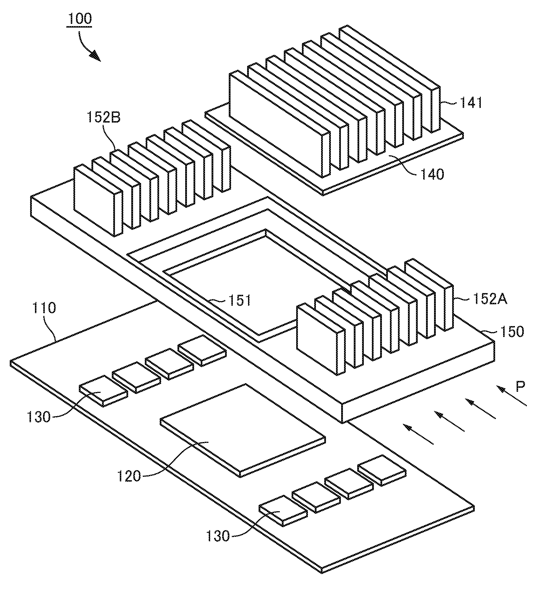
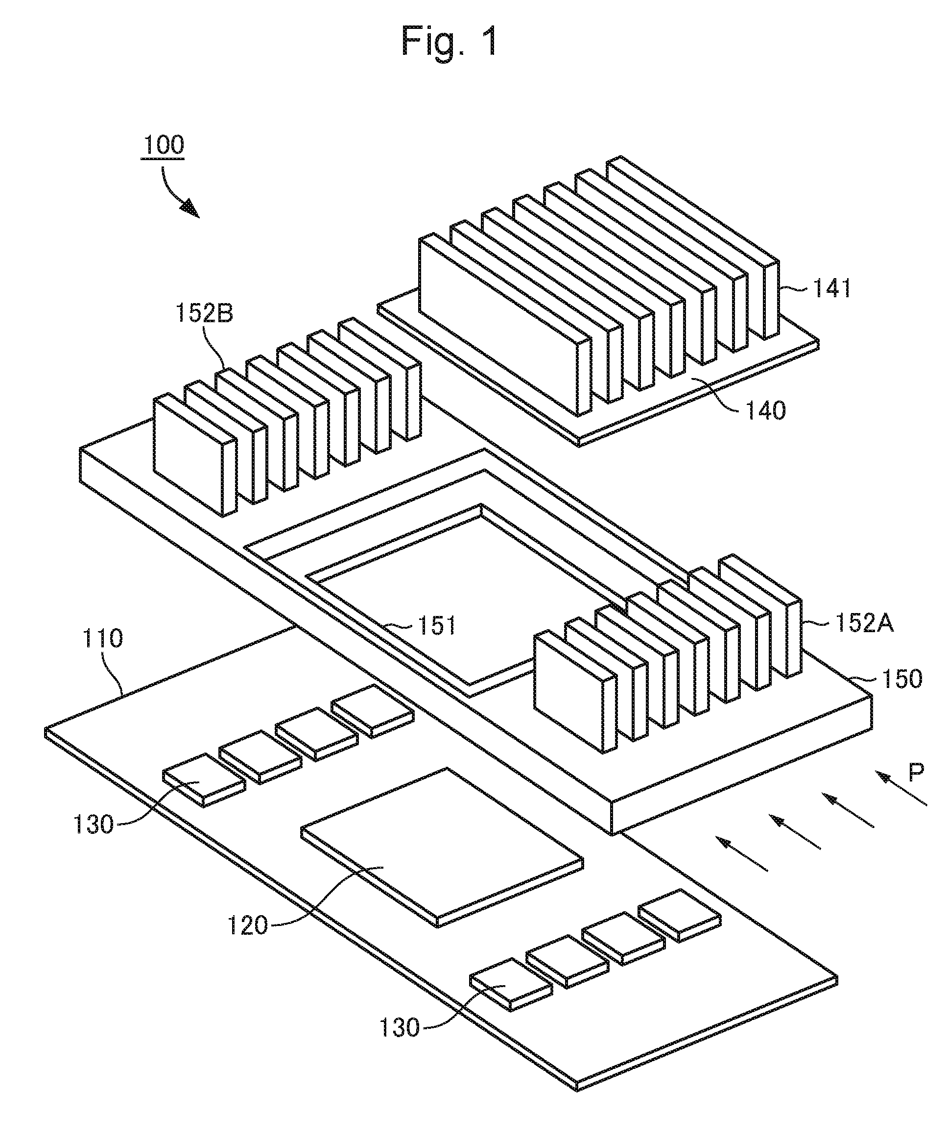
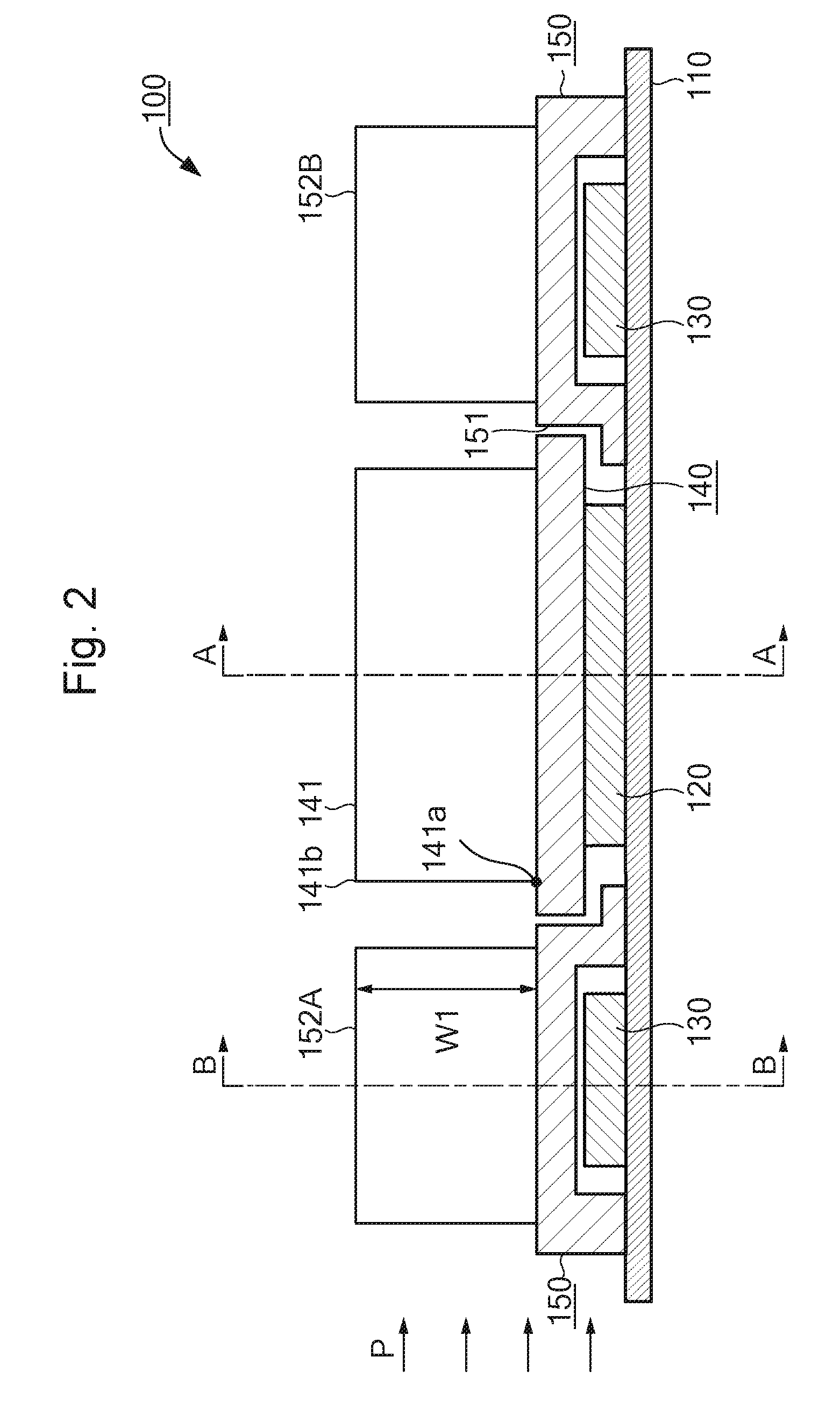
[0073]Referring to FIG. 7, it is assumed that air flows in from outside of the electronic device in a direction of the arrow P, for example.

[0074]Referring to FIG. 7, the air flow which flows in from the outside of the electronic device flows through the fins for frame 152MA, the fins for heat dissipation unit 141, and the fins for frame 152MB in this order.

[0075]In this case, the fins for frame 152MA and 152MB are provided above the memories 130. Therefore, the fins for frame 152MA and 152MB mainly radiate heat generated by the memories 130 into the air. The fins for frame 152MA and 152MB are also provided close to the CPU 120. In this structure, the fins for frame 152MA and 152MB can radiate heat generated by the memories 130 and heat generated by the CPU 120 into the air. Also, since the heat dissipation unit 140 is thermally coupled with the CPU 120, the fins for heat dissipation unit 141 radiate heat...


PUM


Abstract

A device includes: a substrate; a heat-generating component which is mounted on a first surface of the substrate; a heat sink which is thermally coupled with the heat-generating component; and a frame which is attached on the first surface of the substrate. The heat sink includes a first fin extending in a direction away from the first surface, and the frame includes a second fin which is arranged on the frame, and the second fin extends in a direction away from the first surface. The first fin extends higher than bottom side of the second fin toward top side of second fin.

Description

[0001]This application is based upon and claims the benefit of priority from Japanese Patent Application No. 2015-057532, filed on Mar. 20, 2015, the disclosure of which is incorporated herein in its entirety by reference.TECHNICAL FIELD[0002]The embodiments of the present invention relate to a device and a cooling structure. More particularly, it relates to a device and a cooling structure for cooling heat-generating components mounted on a substrate.BACKGROUND ART[0003]Patent Document 1 discloses a technique regarding a cooling structure of a semiconductor module. Each heat-generating component (LSI (Large Scale Integration) 1) is thermally connected to a heat dissipation unit (heat sink 3). Therefore, heat of each heat-generating component is transferred to corresponding heat dissipation unit to cool a plurality of heat-generating components simultaneously. In this structure, a plurality of heat dissipation units can cool heat of a plurality of heat-generating components.[0004]Pa...

Claims


Application Information

Patent Timeline
IPC IPC(8): H05K1/02F28F3/02H05K1/18
CPCH05K1/0203F28F3/02H05K1/181G06F1/20H01L23/36H01L23/3672H01L23/3675H01L23/467
Inventor MATSUMOTO, YUKI
Owner NEC CORP
Why Eureka
Try Eureka