Laser device

Active Publication Date: 2018-08-02
FANUC LTD
View PDF0 Cites 2 Cited by
  • Summary
  • Abstract
  • Description
  • Claims
  • Application Information

AI Technical Summary

Benefits of technology

[0013]A laser device provided by the present invention is capable of cooli

Problems solved by technology

This makes it difficult to cool a heat-generating part e

Method used


Image

  • Laser device
  • Laser device
  • Laser device

Examples


Example

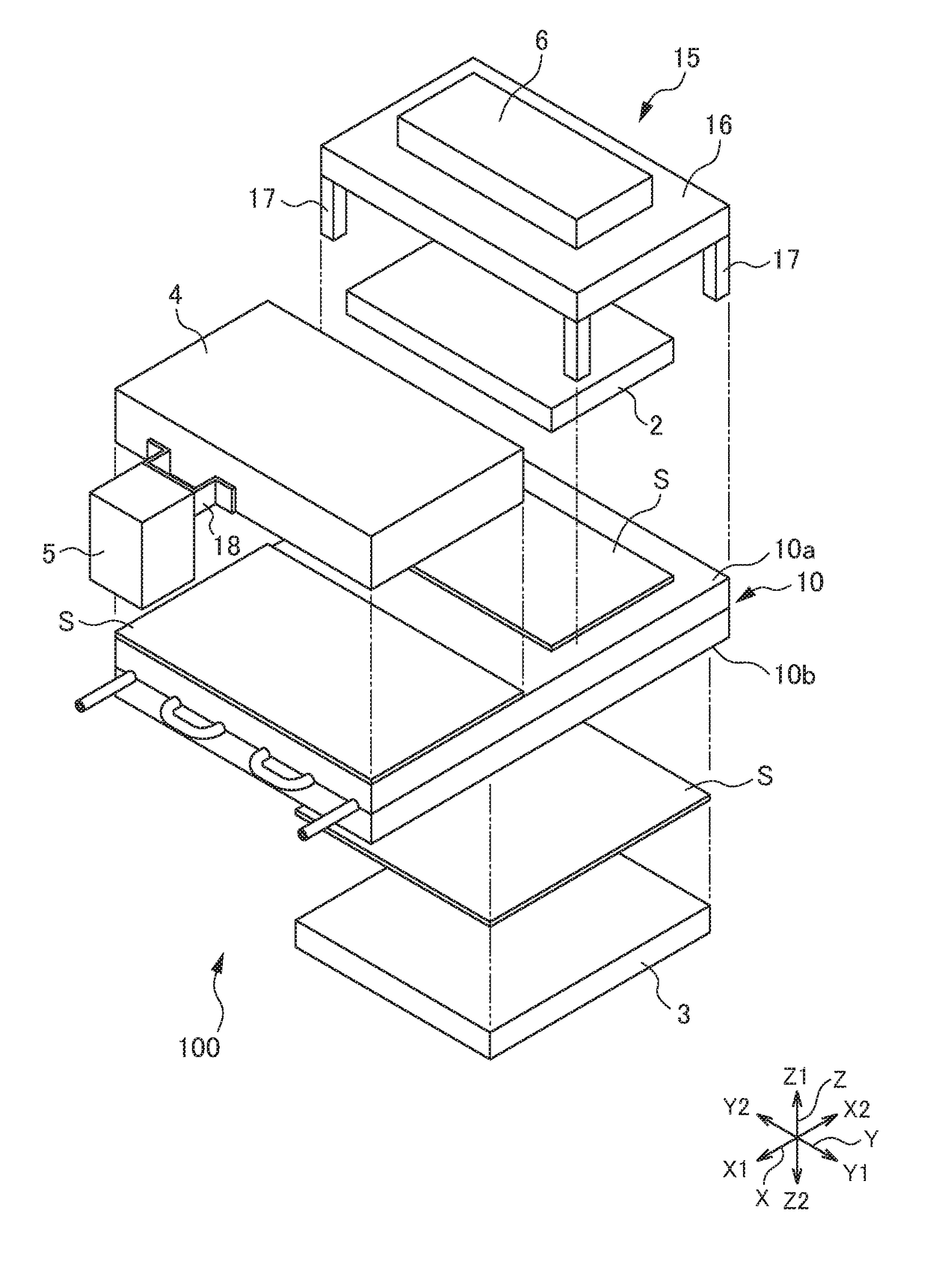
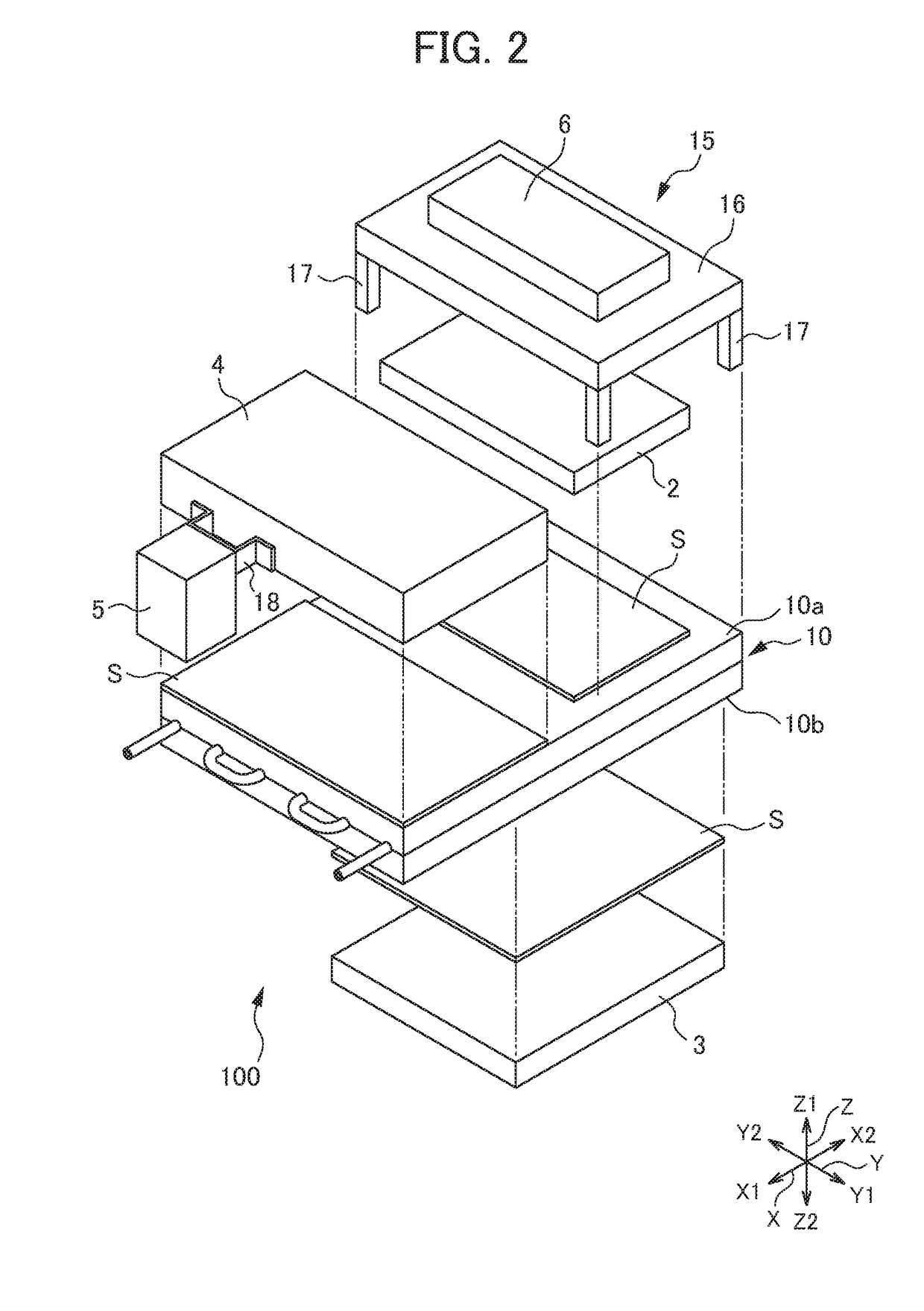
[0023]An embodiment of the present invention will be described below. All the drawings accompanying the present specification are schematic views. To facilitate understanding, etc., illustration of each part is changed from an actual object or exaggerated in terms of a shape, a scale, or a dimensional aspect ratio, for example. In the drawings, hatching showing a cross section of a member is omitted, where appropriate. In the present specification, etc., one crosswise direction of a laser device 1 an X (X1-X2) direction. A crosswise direction perpendicular to the X direction is a Y (Y1-Y2) direction. The thickness direction of the laser device 1 (a direction perpendicular to an X-Y plane) is a Z (Z1-Z2) direction. The shape of the laser device 1 viewed in the thickness direction (Z direction) is not limited to a rectangular shape as in this embodiment, but it may also be a square shape or a trapezoidal shape, for example.

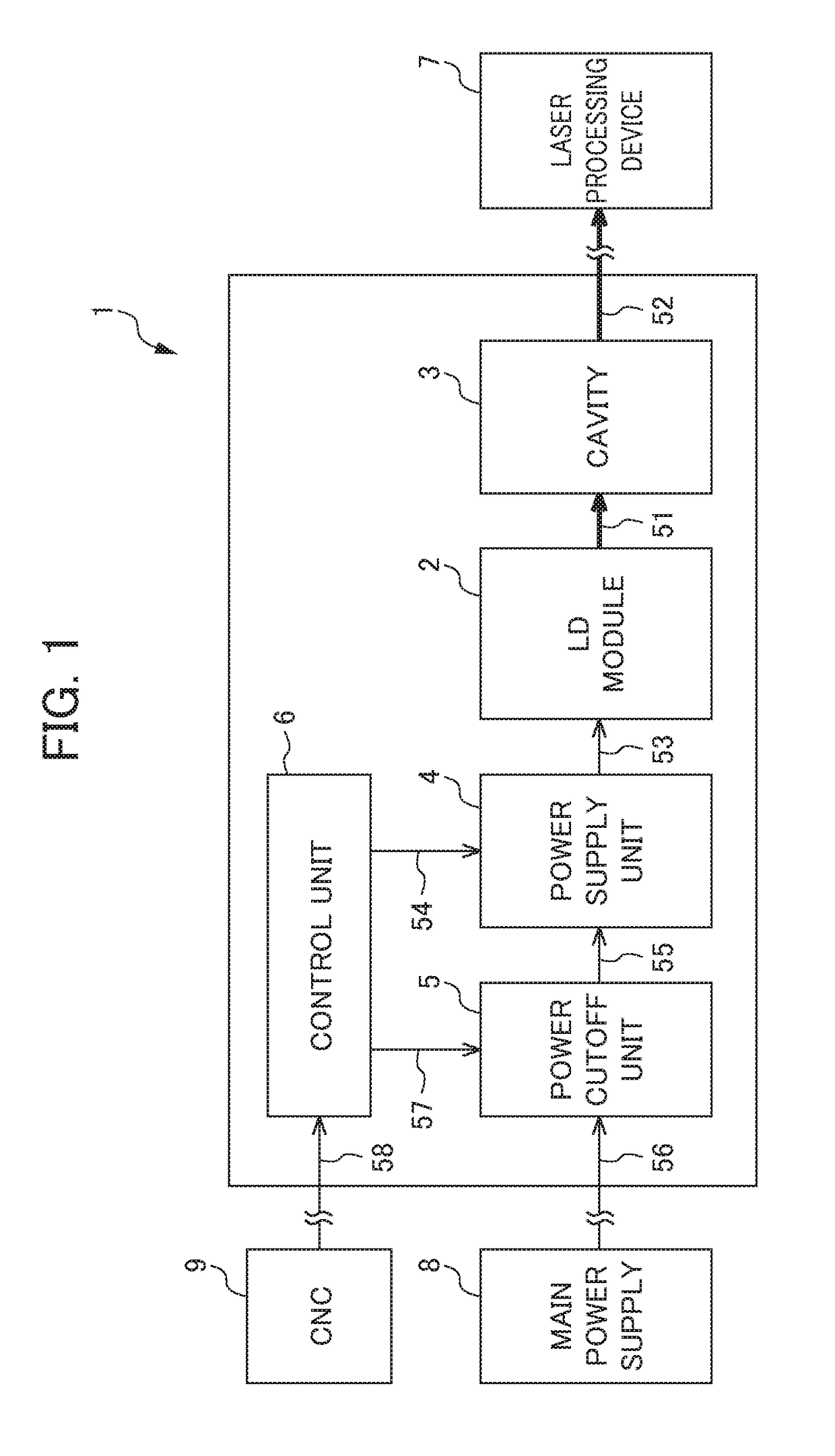
[0024]FIG. 1 is a block diagram showing the functional configu...


PUM

PropertyMeasurementUnit
Fractionaaaaaaaaaa
Thicknessaaaaaaaaaa
Electrical conductivityaaaaaaaaaa

Abstract

A laser device includes a light-emitting unit that generates a laser beam, an amplification unit that amplifies the laser beam generated by the light-emitting unit, a power supply unit that supplies power for generating the laser beam to the light-emitting unit, a plate-like cooling unit including a first cooling surface and a second cooling surface positioned opposite to the first cooling surface, and a housing in which the light-emitting unit, the amplification unit, the power supply unit, and the cooling unit are housed. The power supply unit and the light-emitting unit are arranged adjacent to the first cooling surface of the cooling unit. The amplification unit is arranged adjacent to the second cooling surface of the cooling unit.

Description

[0001]This application is based on and claims the benefit of priority from Japanese Patent Application No. 2017-016675, filed on Feb. 1, 2017, the content of which is incorporated herein by reference.BACKGROUND OF THE INVENTIONField of the Invention[0002]The present invention relates to a laser device that outputs a laser beam.Related Art[0003]Conventionally, a laser beam has been used for cutting of metal or nonmetal, welding, etc. A laser device that outputs a laser beam of this type includes a power supply unit, a laser diode (LD) module, a cavity, etc. All these parts generate heat while running (hereinafter also called “heat-generating parts”). Hence, these heat-generating parts are required to be cooled during operation of the laser device. In the conventional laser device, these heat-generating parts are cooled by using a water-cooling plate with a water-cooling pipe embedded in the water-cooling plate, for example (see patent documents 1 and 2, for example).[0004]Patent Docu...

Claims


Application Information

Patent Timeline
IPC IPC(8): B23K26/06B23K26/21B23K26/38B23K37/00H01S5/023H01S5/0233
CPCB23K26/0626B23K26/21B23K26/38B23K37/003H01S3/0405H01S3/0407H01S5/02423H01S5/023H01S5/0233H01S3/2308H01S5/02216H01S5/02438H01S5/0235H01S5/02251
Inventor HONDA, MASAHIROMATSUDA, MUNEKAZU
Owner FANUC LTD
Why Eureka
Try Eureka