Generator in particular for a wind turbine

Inactive Publication Date: 2012-04-19
SIEMENS AG
View PDF4 Cites 2 Cited by
  • Summary
  • Abstract
  • Description
  • Claims
  • Application Information

AI Technical Summary

Benefits of technology

[0006]It is therefore an object of the present invention to provide a

Problems solved by technology

In generators heat losses occur, mainly from electromagnetic losses (Joule losses, iron losses, copper losses, .
In permanent magnet generators these loss

Method used


Image

  • Generator in particular for a wind turbine
  • Generator in particular for a wind turbine

Examples


Embodiment Construction

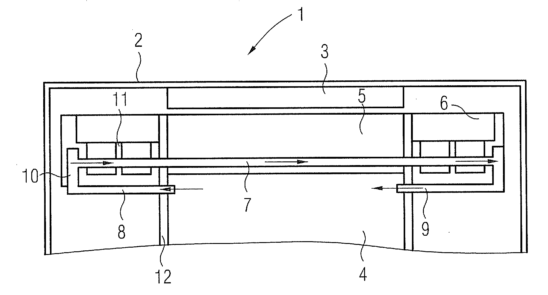
[0022]FIG. 1 shows a detail of a generator 1 in a cross-sectional view. The generator 1 comprises a rotor 2, comprising a number of magnets 3, arranged in circumferential direction.

[0023]A stator 4 comprises a stator lamination 5 with end windings 6 on both sides of the stator lamination 5.

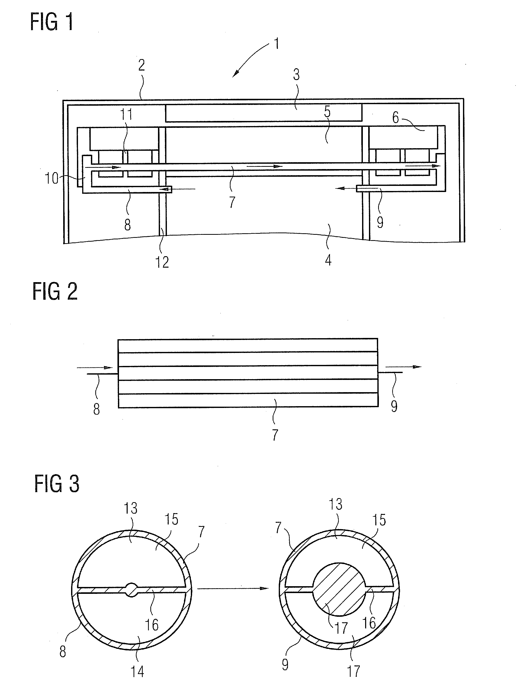
[0024]When rotor 2, which has a circular shape, is rotated around the stator 4, an electric current is generated in the windings of the stator lamination 5. During movement of the rotor 2 heat losses occur so that the stator lamination 5 is heated up. In order to dissipate the heat a number of cooling pipes 7 are provided within the stator lamination 5. A large number of cooling pipes 7 is arranged in parallel along the circumferential direction of stator 4. In the embodiment of FIG. 1 all cooling pipes 7 are connected parallel, a pump (not shown) is used for conveying a coolant through the cooling pipes 7.

[0025]Each cooling pipe 7 comprises an inlet 8 and an outlet 9 the arrows indicate the flow ...


PUM


Abstract

A generator in particular for a wind turbine is proposed. The generator has a rotor with a number of circumferentially arranged magnets. The generator has a stator with a lamination and conductors. The generator has a cooling device for cooling the stator. The cooling device has cooling pipes arranged along the stator lamination and filled with a coolant.

Description

CROSS REFERENCE TO RELATED APPLICATIONS[0001]This application claims priority of European application No. 10187373.5 filed Oct. 13, 2010, which is incorporated by reference herein in its entirety.FIELD OF THE INVENTION[0002]The present invention relates to a generator, in particular for a wind turbine, comprising a rotor with a number of circumferentially arranged magnets, a stator with lamination and conductors and a means for cooling the stator.BACKGROUND OF THE INVENTION[0003]Such generators are components of wind turbines, which are provided with a rotor shaft which is part of the electrical generator producing electricity during movement of the rotor relative to the stator. The stator comprises a lamination and conductors, the rotor comprises a number of permanent magnets or electrically charged magnets so that an electric voltage is generated when the rotor is turned.[0004]In generators heat losses occur, mainly from electromagnetic losses (Joule losses, iron losses, copper lo...

Claims


Application Information

Patent Timeline
IPC IPC(8): F03D9/00H02K9/19
CPCF28D2021/0028F28F13/08Y02E10/725H02K7/1838H02K9/19H02K1/20Y02E10/72H02K9/197
Inventor LE BESNERAIS, JEAN
Owner SIEMENS AG
Why Eureka
Try Eureka