Projection-type display apparatus

Inactive Publication Date: 2008-09-25
CANON KK
View PDF5 Cites 3 Cited by
  • Summary
  • Abstract
  • Description
  • Claims
  • Application Information

AI Technical Summary

Benefits of technology

[0009]An object of the present invention is to provide a projection-type display appara

Problems solved by technology

However, the reflectance of the reflection mirror is not 100%, so that heat is held on a reflective surface of the reflection mirror although it is slight, and a temperature difference is generated between a reflective surface side and a rear surface side of the reflection mirror due to the influence of the heat, which results in a problem that the reflection mirror will be deformed due to a bimetallic effect.
For example, in the case of cooling a reflect

Method used


Image

  • Projection-type display apparatus
  • Projection-type display apparatus
  • Projection-type display apparatus

Examples


Example

Embodiment 1

[0024]Although a detailed illustration is omitted, the projection-type display apparatus of this embodiment modulates a projection light from a lamp of an illumination system optical unit with an optical modulation device as is the case with an ordinary projector, and thereafter, projects the light on a screen with a projection optical system in a magnified form. The projection optical system includes one or more reflection mirrors, and cools a reflective surface of the reflection mirror with air from a cooling fan.

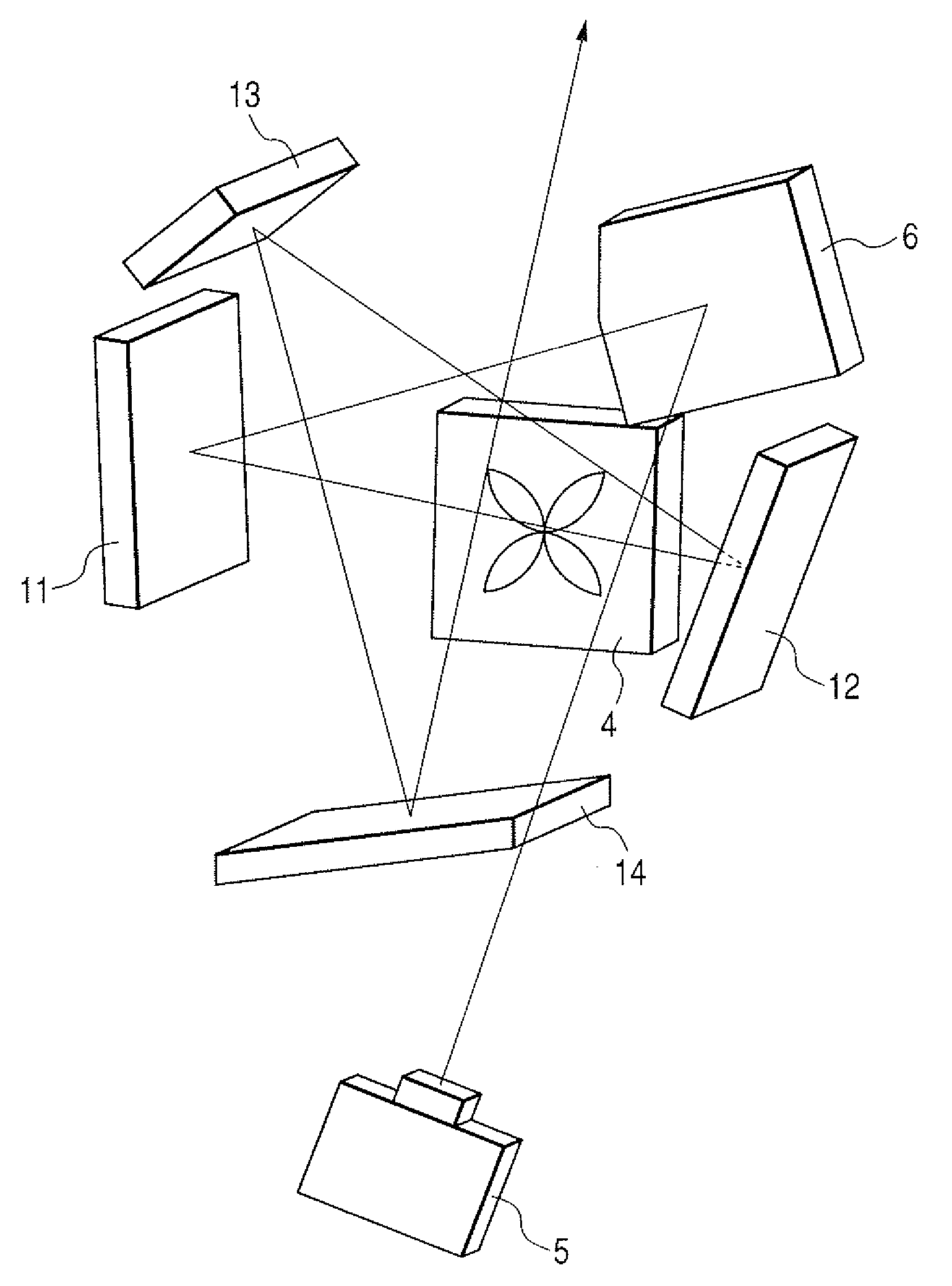
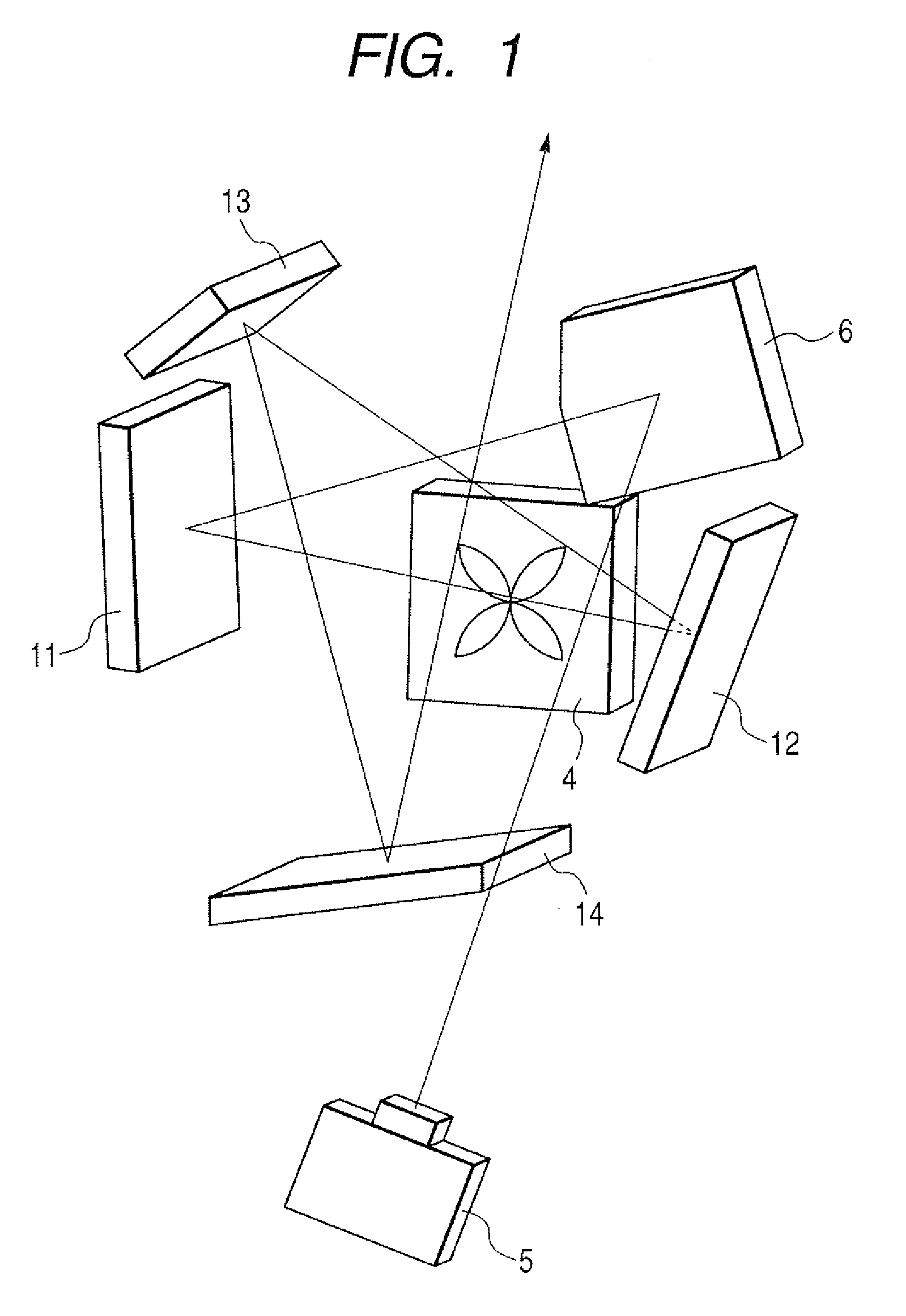
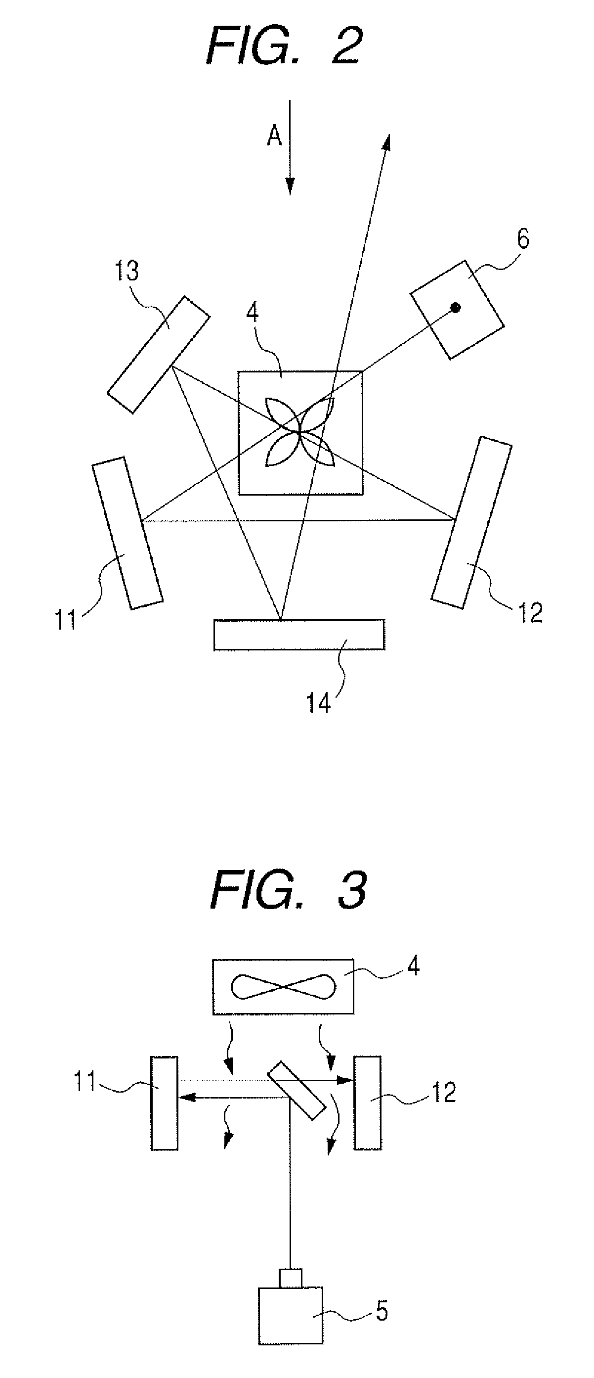
[0025]More specifically, as illustrated in FIGS. 1 to 3, a light beam from a lamp is guided to the first surface reflection mirror 11 by the small reflection mirror 6 that changes the light traveling direction by about 90° in a horizontal direction. After that, the light beam is sequentially reflected by the second surface reflection mirror 12, the third surface reflection mirror 13, and the fourth surface reflection mirror 14, and projected on a screen or the...

Example

Embodiment 2

[0045]As illustrated in FIG. 8, a projection-type display apparatus of this embodiment guides a light beam from a lamp of an illumination system optical unit 5 to the first surface reflection mirror 11 by the small reflection mirror 6 that changes the light traveling direction by about 90° in a horizontal direction. After that, the light beam is sequentially reflected by the second surface reflection mirror 12, the third surface reflection mirror 13, and the fourth surface reflection mirror 14, and projected on a screen (not illustrated) or the like placed ahead of the mirrors. At this time, the respective reflection mirrors 6 and 11 to 14 are air-cooled by the cooling fan 4 placed on the side of the reflection mirrors 6 and 11 to 14 so that the respective reflection mirrors 6 and 11 to 14 are not deformed by the bimetallic effect caused by the influence of heat as described above.

[0046]The projection-type display apparatus of Embodiment 1 of the present invention has su...

Example

Embodiment 3

[0049]As illustrated in FIG. 9, a projection-type display apparatus of this embodiment guides a light beam from the lamp of the illumination system optical unit 5 to the first surface reflection mirror 11 by the small reflection mirror 6 that changes the light traveling direction by about 90° in a horizontal direction. After that, the light beam is sequentially reflected by the second surface reflection mirror 12, the third surface reflection mirror 13, and the fourth surface reflection mirror 14, and projected on a screen (not illustrated) or the like placed ahead of the mirrors. At this time, the respective reflection mirrors 6 and 11 to 14 are air-cooled by the cooling fan 4 disposed on the side of the reflection mirrors 6 and 11 to 14 so that the respective reflection mirrors 6 and 11 to 14 are not deformed by the bimetallic effect caused by the influence of heat as described above.

[0050]The projection-type display apparatus of this embodiment has substantially the s...


PUM


Abstract

Provided is a projection-type display apparatus which can efficiently cool a reflection mirror with a small number of cooling fans. The projection-type display apparatus is a display apparatus for modulating a projection light from a lamp by an optical modulation device and then projecting the light on a screen in a magnified form by a projection optical system, which has a configuration in which the projection optical system includes at least one reflection mirror, and a reflective surface of the reflection mirror is air-cooled by a cooling fan, wherein an air flow rate of the cooling fan is controlled based on a projection image information.

Description

BACKGROUND OF THE INVENTION[0001]1. Field of the Invention[0002]The present invention relates to a projection-type display apparatus such as a projector, and more specifically, to cooling of a reflection mirror for image formation of the projection-type display apparatus.[0003]2. Description of the Related Art[0004]Hitherto, for the purpose of reducing the size and thickness of a projection-type display apparatus, a rear projection display using an oblique projection system has been proposed (Japanese Patent Application Laid-Open No. 2001-255462). Specifically, the oblique projection system is a system such that a light projected from a lamp is sequentially reflected by a plurality of reflection mirrors and is projected onto a screen or the like placed ahead of the reflection mirrors. Along with the recent size reduction of an equipment and the increase in definition (display resolution) of an image, the reflection mirror has become an essential part which is required to have a high...

Claims


Application Information

Patent Timeline
IPC IPC(8): G03B21/16
CPCG03B21/16
Inventor NABETA, NOBORU
Owner CANON KK
Why Eureka
Try Eureka