Goal to ground monitor

a technology of goal monitor and monitor, applied in the direction of mechanical visible signalling, identification means, instruments, etc., can solve the problems of dangerous condition, goal slipping, and un-staked and loose goals

Active Publication Date: 2010-06-17
RTC IND
View PDF22 Cites 6 Cited by
  • Summary
  • Abstract
  • Description
  • Claims
  • Application Information

AI Technical Summary

Benefits of technology

[0017]In an alternate embodiment, the contact arm and indicator arm include interfering portions configured to cooperate with one another. In this embodiment, in the ready position, the contact arm interfering portion overlies the indicator arm interfering portion to maintain the indicator arm in the ready position. After movement to the upset position, the contact arm interfering portion prevents resetting of the indicator arm without upward pivoting of the contact arm.

Problems solved by technology

However, at times, due to various reasons, the goals become un-staked and loose.
This can cause a hazardous condition.
There is a danger of goals tipping over.
Such tipping has resulted in numerous serious injuries, often of young children, with some victims as young as 3 and 4 years of age.
Indeed, it is estimated that tipping over of goals results in between 90 and 200 serious injuries annually, and that such injuries can require hospitalization.
However with some degree of force the goal can tip over.
A small child climbing on the net or crossbar may also be sufficient to reduce the stability of the goal.
Because of the weight of these soccer goals, averaging between about 150-500 pounds, the results of a goal striking a person can be devastating.
However, due to the sheer number of goals and the multi-usage of the fields, as well as other factors including, for example, changing soil conditions due to, for example, excessive rain or drought, this has proven a much more challenging and elusive task.

Method used


Image

  • Goal to ground monitor
  • Goal to ground monitor
  • Goal to ground monitor

Examples


Embodiment Construction

[0039]While the present invention is susceptible of embodiment in various forms, there is shown in the figures and photographs and will hereinafter be described a presently preferred embodiment with the understanding that the present disclosure is to be considered an exemplification of the invention and is not intended to limit the invention to the specific embodiment illustrated.

[0040]It should be further understood that the title of this section of this specification, namely, “Detailed Description Of The Invention”, relates to a requirement of the United States Patent Office, and does not imply, nor should be inferred to limit the subject matter disclosed herein.

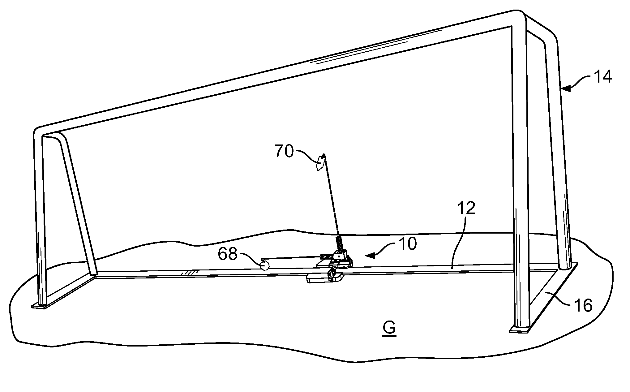
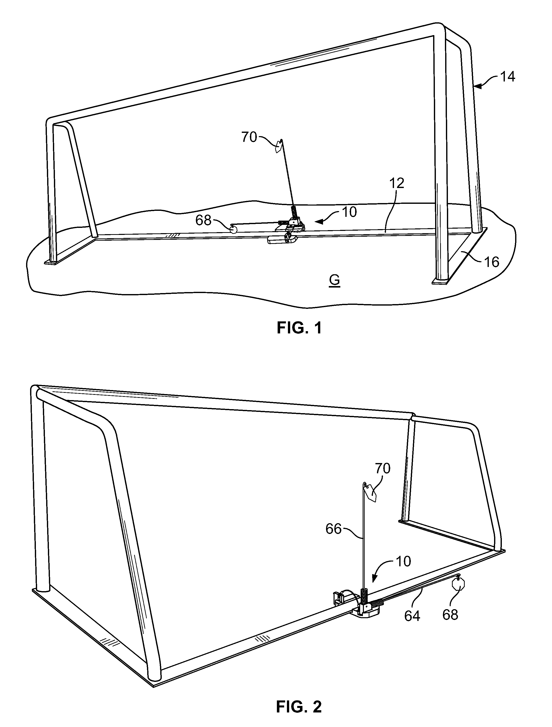
[0041]Referring to the figures and in particular to FIGS. 1 and 2, there is shown an embodiment of a goal to ground monitor 10 embodying the principles of the present invention. The monitor 10 is shown at the rear ground bar or rear ground shoe 12 (collectively, rear ground bar) of a soccer goal 14. It will be appreciated ...


PUM


Abstract

A goal to ground indicator device indicates a ready and/or upset condition of a ground supported goal such as a soccer goal that has at least one bar that lies in contact with the ground. The indicator device includes a base plate, a contact arm mounted to the base plate and movable relative to the base plate and an indicator arm mounted to the base plate for cooperation with the contact arm. The contact arm and a portion of the base plate are configured for contact with the bar. The indicator arm is movable relative to the contact arm between a ready position and an upset position. The indicator arm is positioned such that a portion of the contact arm cooperates with a portion of the indicator arm to temporarily maintain the indicator arm in the ready position. A biasing element biases the indicator arm to the upset position. The contact arm resting in the base plate cooperates with the indicator arm against the biasing element to maintain the indicator arm in the ready position when the bar overlies the contact arm. When the bar is moved from the contact arm, the biasing element exerts a force to move the indicator arm from the ready position to move the contact arm from the base plate to disengage the indicator arm and to continue moving the indicator arm to the upset position. The contact arm can be mounted directly to the bar.

Description

CROSS-REFERENCE TO RELATED APPLICATION DATA[0001]This application claims the benefit of priority of Provisional U.S. Patent Application Ser. No. 61 / 122,471, filed Dec. 15, 2008, entitled, “GOAL TO GROUND MONITOR”, which application is incorporated herein by reference.BACKGROUND OF THE INVENTION[0002]The present invention relates to a device for monitoring the present and past ground contact of moveable sport goals. In particular the invention relates a device to monitor the ground contact of soccer goals and to provide a visual indication of ground contact status of the goal.[0003]Soccer is one of, and perhaps the most popular sport in the world. In some instances, soccer goals are fixed, or set securely (permanently or semi-permanently) into the ground. In other instances, soccer fields can be shared (e.g., also used as lacrosse fields), and as such the goals are moveable.[0004]Typically, the goals are staked or anchored into the ground to secure the goals in place. However, at tim...

Claims


Application Information

Patent Timeline
Patent Type & Authority Applications(United States)
IPC IPC(8): G01D21/00
CPCA63B63/004G08B5/02A63B71/0054
Inventor DEMPSEY, GREGORY S.
Owner RTC IND
Why Eureka
Try Eureka