

Supercharging device
- Summary
- Abstract
- Description
- Claims
- Application Information
AI Technical Summary
Benefits of technology
Problems solved by technology
Method used
Image

Examples
Embodiment Construction
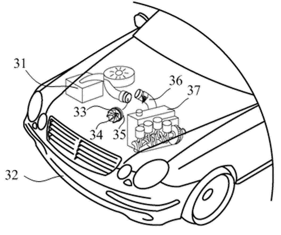
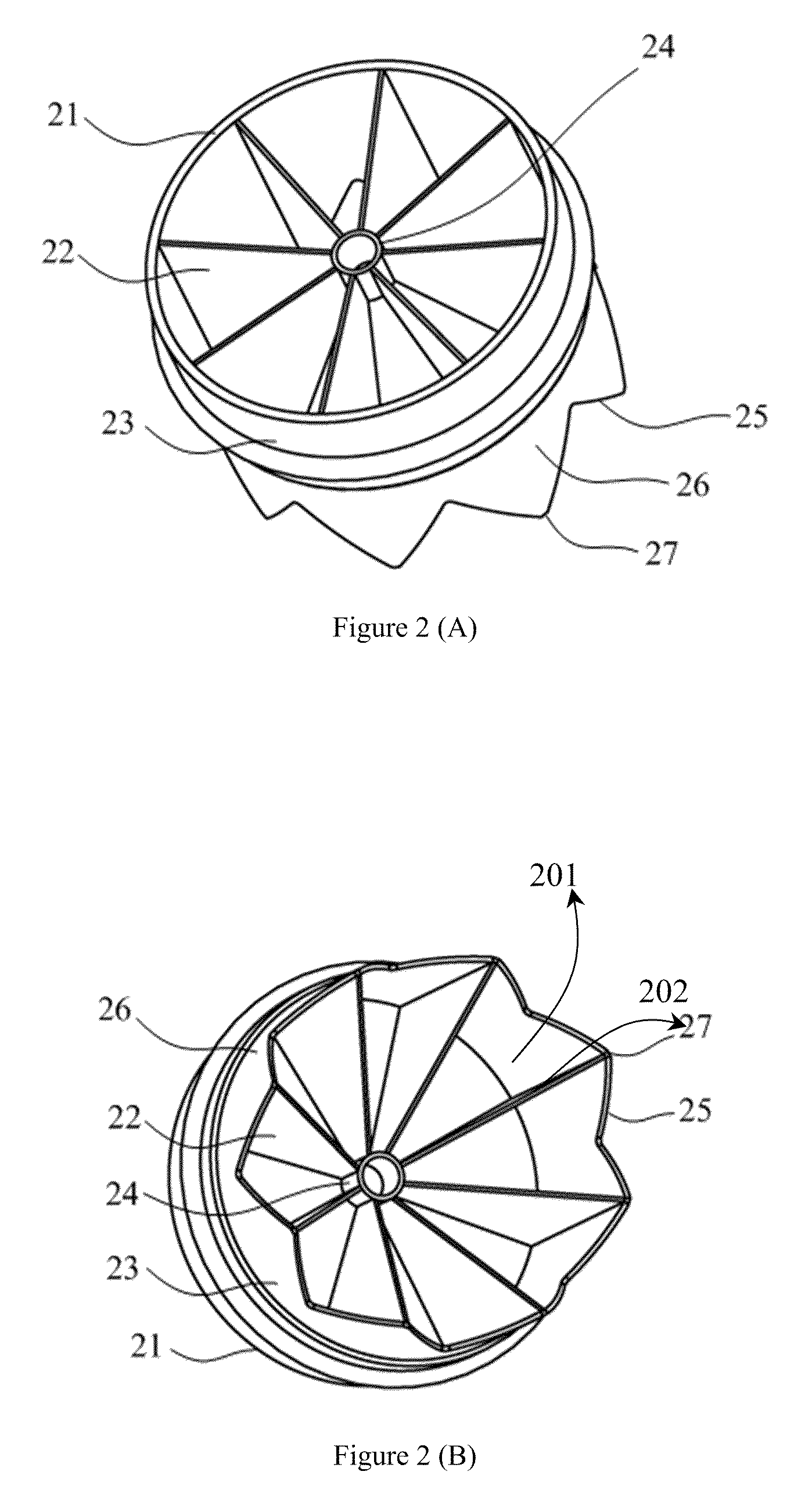
[0027]FIG. 2 is a schematic view showing the supercharging device in accordance with one preferred embodiment of the present invention, which comprises the secondary end 21, blade 22, frame body 23, axial structure 24, primary end 25, serration structure 26 and peak portion 27. The supercharging device provided by the present invention mainly consists of frame body 23, axial structure 24 and a plurality of blades 22. Whereat, the frame body 23 is being formed into a shape of cylindrical tube, and the port of primary end 25 of frame body 23 is being formed into a serration shape comprising a plurality of serration structure 26; however, the port of secondary end 21 of the frame body 23 is being formed into a smooth plane instead. There is axial structure 24 being constructed at the axis portion of the frame body 23, and a plurality of blades 22 are being connected to both the frame body 23 and axial structures 24. Wherein, blade 22 is being formed into a trapezoidal-shaped blade, whi...
PUM
 Abstract
Description
Claims
Application Information