Fuel injection system for internal combustion engine with injector isolator ring

a fuel injection system and injector technology, applied in the field of internal combustion engines, can solve the problems of monotonic increase of the axially directed force/deflection rate of the isolator

Inactive Publication Date: 2010-07-15
FORD GLOBAL TECH LLC
View PDF18 Cites 10 Cited by
  • Summary
  • Abstract
  • Description
  • Claims
  • Application Information

AI Technical Summary

Benefits of technology

[0010]It is an advantage of a fuel injection system according to the present invention that objectionable ticking noise, which is particularly prevalent in engines having direct cylinder injectors, will be avoided, while at the same time protecting injector tip seals from harm which could otherwise occur as a result of an overly compliant mounting system.
[0011]It is an advantage of a system according to the present inventi

Problems solved by technology

This causes the axially directed force/deflectio

Method used


Image

  • Fuel injection system for internal combustion engine with injector isolator ring
  • Fuel injection system for internal combustion engine with injector isolator ring
  • Fuel injection system for internal combustion engine with injector isolator ring

Examples


Embodiment Construction

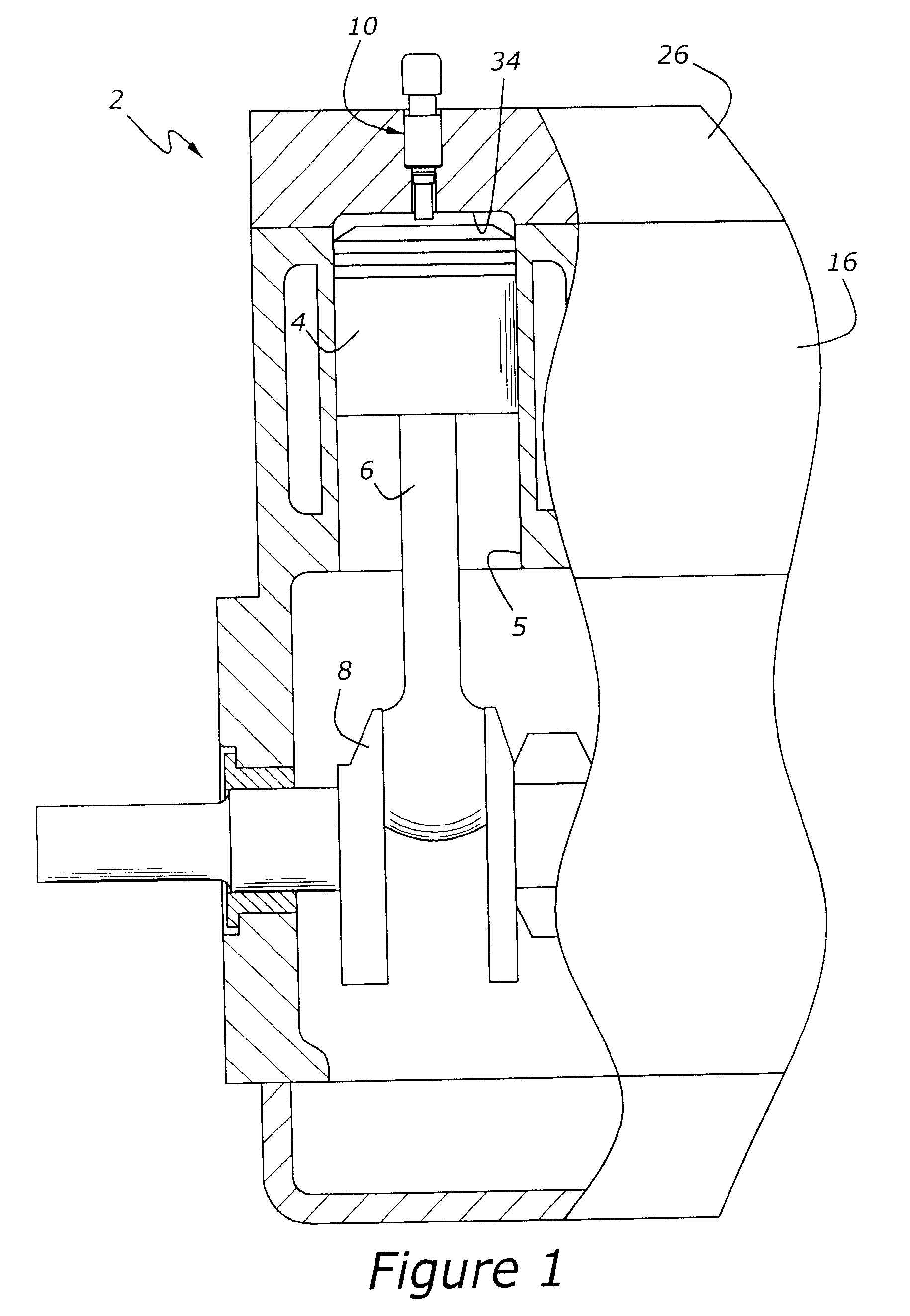
[0020]FIG. 1 illustrates an engine, 2, having a crankshaft, 8, with a piston, 4, and a connecting rod, 6, attached thereto, for reciprocating motion within a cylinder, 5, formed in a cylinder block, 16. A cylinder head, 26, is mounted at the top of engine 2. A fuel injector, 10, is mounted through cylinder head 26 so as to supply fuel directly to the combustion chamber defined by cylinder head 26 and piston 4.

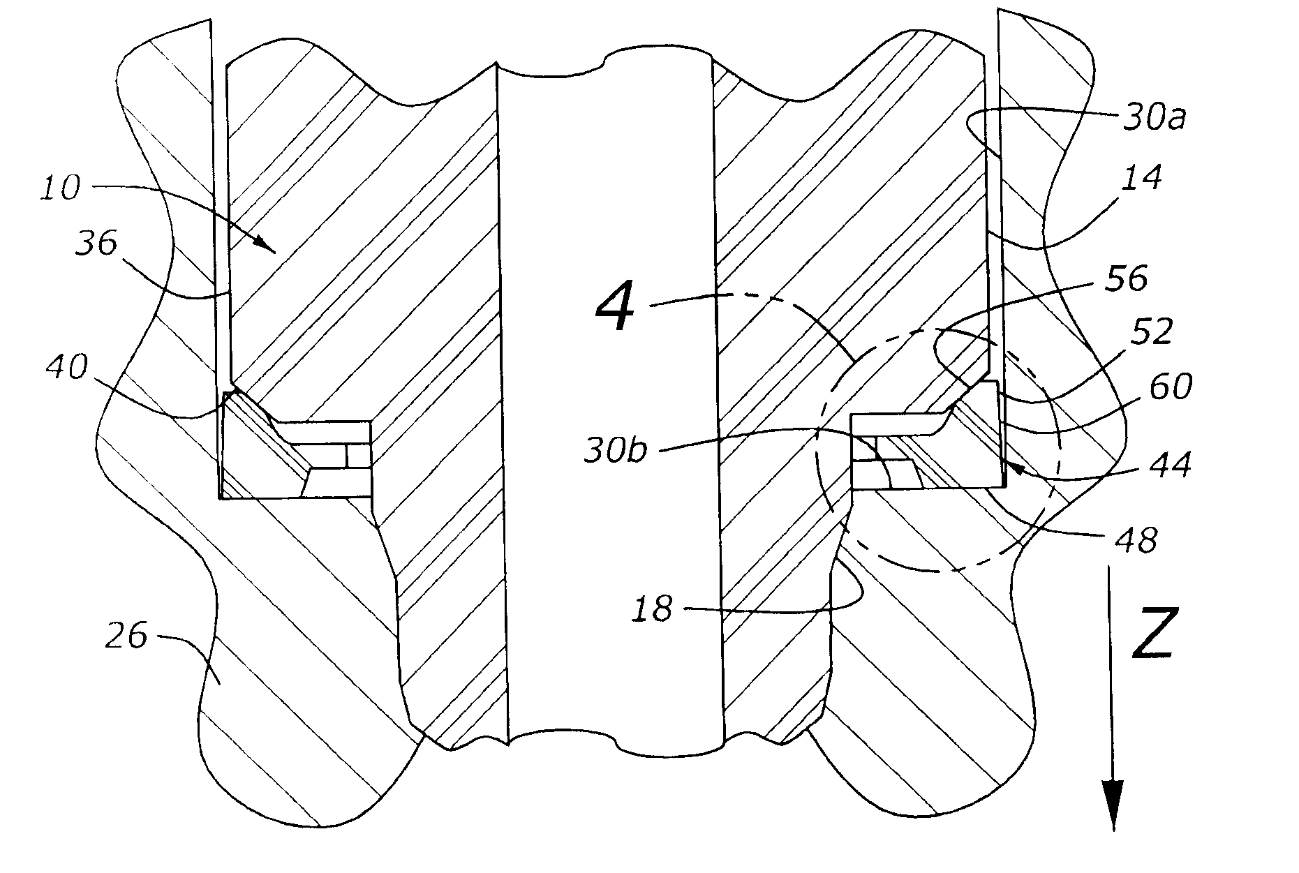
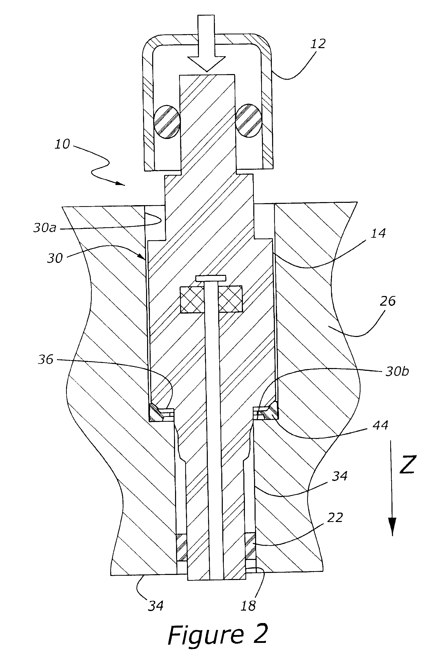
[0021]FIG. 2 is a partially schematic representation of a fuel injection system having an injector isolator according to an aspect of the present invention. Fuel injector 10 receives fuel through a supply system including a fuel rail cap, 12, which is mounted to the top of injector 10. Injector 10 has a generally cylindrical outer body, 14, which is mounted within an injector pocket, 30, formed in cylinder head, 26. Injector 10 has a tip, 18, with a tip seal, 22, which is preferably formed from a plastics material such as polytetrafluoroethylene. Injector tip 18 extends through...


PUM


Abstract

A fuel injection system for internal combustion engine includes an injector mounted within a pocket formed in the cylinder head, and an isolator which defines a radial clearance gap with the injector pocket. The isolator expands radially outwardly into a clearance gap in response to axially directed force imposed upon the isolator by the injector, so that a dual rate force/displacement effect is achieved by the isolator.

Description

CROSS REFERENCE TO RELATED APPLICATIONS[0001]This application claims priority from U.S. Provisional patent application 61 / 144,520, Filed on Jan. 14, 2009, which is hereby incorporated by reference in its entirety.BACKGROUND OF THE INVENTION[0002]1. Field of the Invention[0003]The present invention relates to an internal combustion engine having fuel injectors mounted within a cylinder head and spraying fuel into the engine's combustion chambers.[0004]2. Related Art[0005]Most spark ignited internal combustion engines used in automotive vehicles have employed fuel systems with either a carburetor, or more recently, multiple fuel injectors mounted in an intake manifold or within individual intake ports. Each of these systems provides fuel to the engine via the intake manifold. Although manifold / port mounted fuel injectors have generally been satisfactory, and indeed, a great improvement as compared with carburetor systems, automotive designers are increasingly moving to the use of dire...

Claims


Application Information

Patent Timeline
IPC IPC(8): F02M61/14
CPCF02M55/004F02M61/14F02M2200/9015F02M2200/16F02M2200/09
Inventor CHERN, YITZONGHOFFMAN, DEANNAFELICE, MARIO JOSEPHHOMCO, STEVENSTOUT, JOSEPH
Owner FORD GLOBAL TECH LLC
Why Eureka
Try Eureka