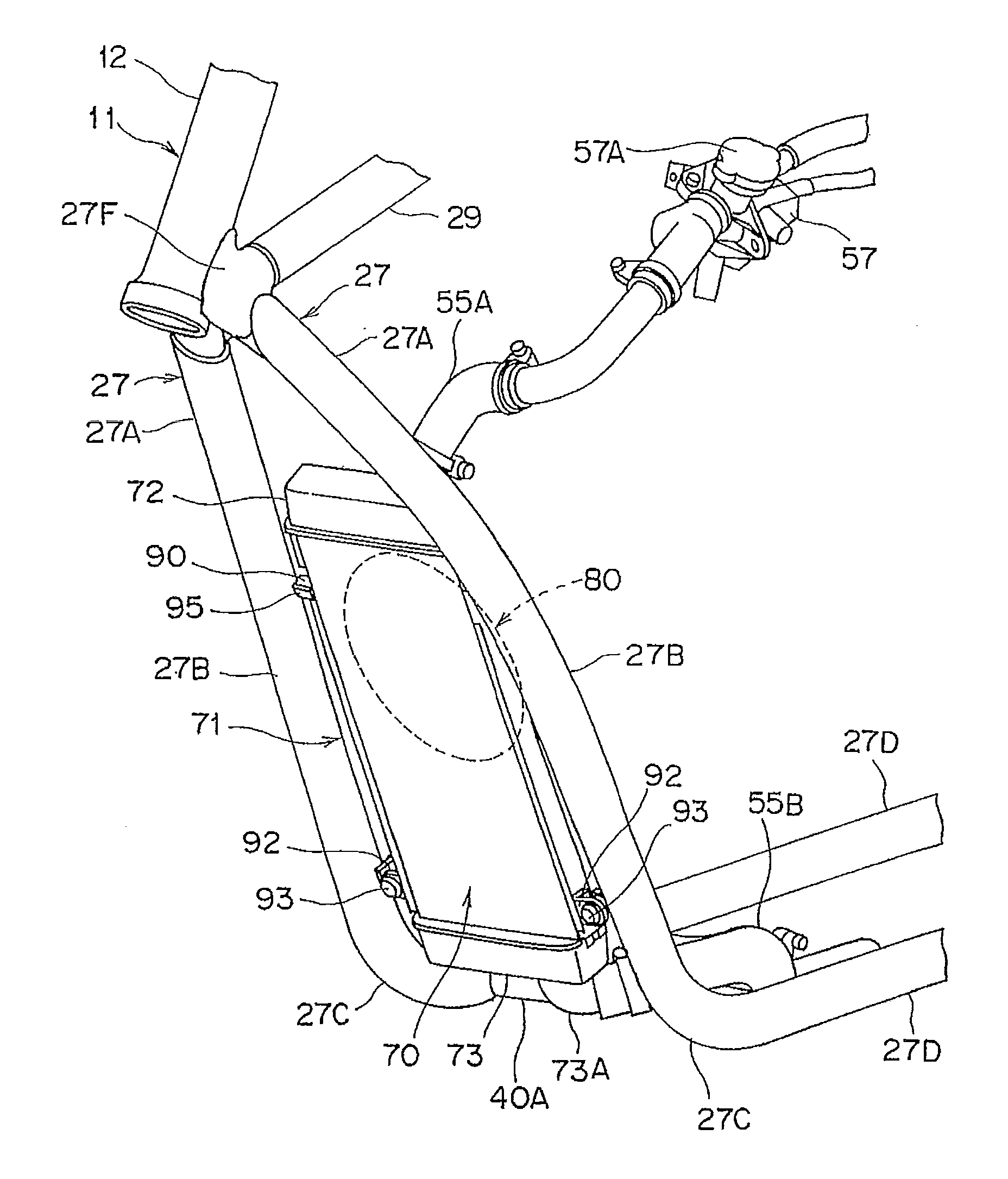
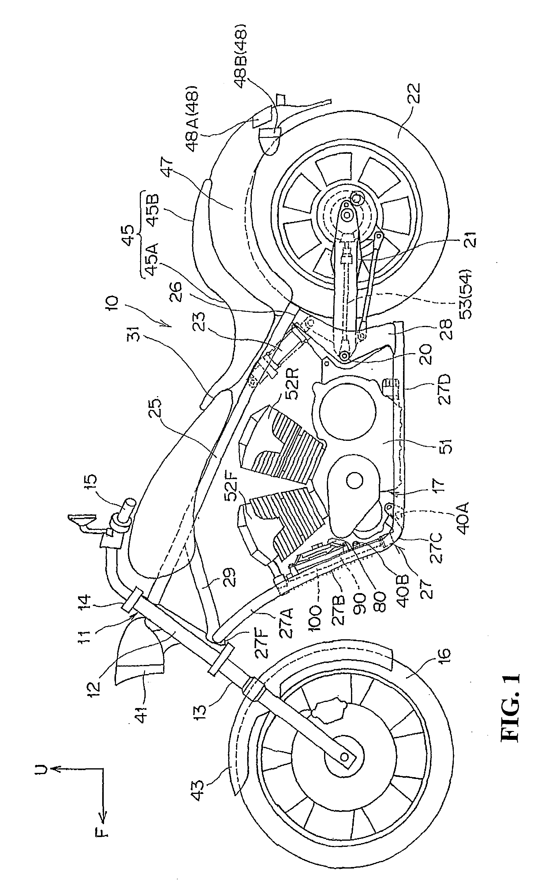
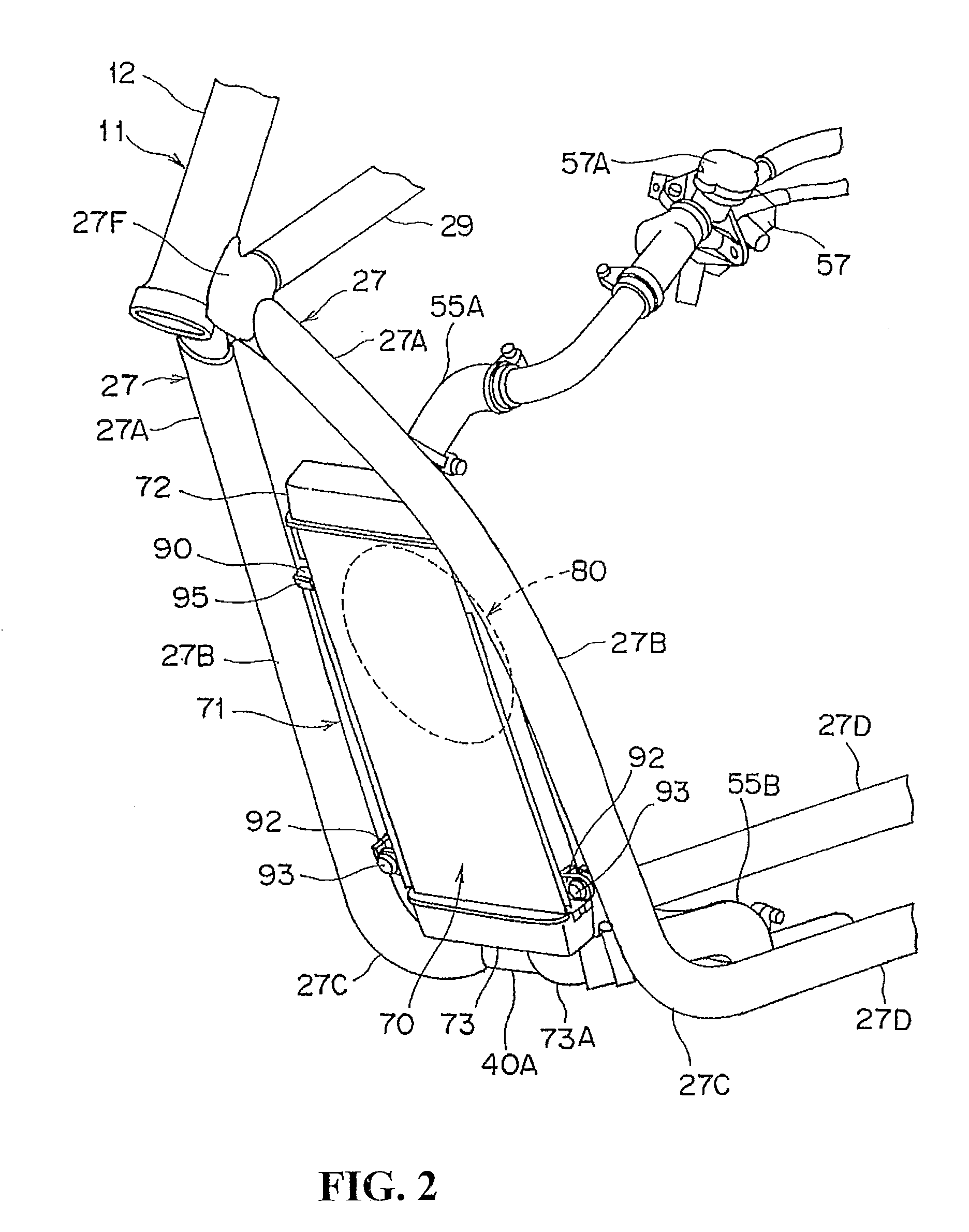
[0012]According to an embodiment of the present invention, the upper portion of each of the down tubes is formed as a curved portion curved in the side view, and the lower portion of each of the down tubes is formed as a linear portion extending linearly downwardlyly from the curved portion in the side view. The radiator then overlaps with the linear portions of the respective down tubes in the side view. Thus, each of the down tubes can be formed in a shape having the curved portion, and the radiator can be erected and disposed in a less visible manner. Since the radiator is erected, the cooling performance can be secured without making the radiator larger. In addition, since the radiator is not highly visible, the external appearance of the vehicle improves.
[0013]In the aforementioned configuration, a radiator grill may be provided in front of the radiator, and the radiator grill may be disposed in a way that the front surface of the radiator grill is positioned along the front surfaces of the curved portions and the linear portions of the respective down tubes. According to this configuration, the radiator grill can be disposed along the down tubes in a less visible manner, each of the down tubes having the curved portion. In addition, this radiator grill can protect the radiator while making the radiator less visible.
[0014]In addition, in the aforementioned configuration, the upper rear portion of the radiator may protrude from the rear surfaces of the down tubes in the side view, and the radiator may be attached to the linear portions of the down tubes at a portion lower than the protruding portion. According to this configuration, the radiator can be attached to the down tubes at a portion where the radiator overlaps with the down tubes, so that this attachment portion can be less visible.
[0015]According to the present invention, the upper portions of the down tubes are formed as the curved portions are each curved in the side view. The lower portions of the respective down tubes are formed as the linear portions each extend linearly downwardly from a corresponding one of the curved portions in the side view. The radiator then overlaps with the linear portions of the down tubes in the side view, so that while each of the down tubes is formed in a shape having the curved portion, the radiator can be erected and disposed in a less visible manner. In addition, since each of the down tubes can be formed in a shape having the curved portion, the radiator surface can be directed to the front of the vehicle body to a large extent as compared with a case where the radiator is disposed between the down tubes each having only a linear portion. Thereby, a flow of air that further improves the cooling performance can be obtained, and the radiator can be made smaller.
[0016]In addition, the radiator grill is provided in front of the radiator and is disposed in a way that the front surface of the radiator grill is positioned along the front surfaces of the curved portions and linear portions of the down tubes. Thus, the radiator grill can be disposed in a less visible manner, and the radiator grill can protect the radiator while making the radiator less visible in the meantime.

