Tiltable welding helmet

a welding helmet and tilting technology, applied in the direction of headwear caps, protective garments, hats, etc., can solve the problems of shell portion returning, not allowing the welder to adjust, and not being sufficiently secur

Inactive Publication Date: 2010-08-26
LINCOLN GLOBAL INC
View PDF18 Cites 20 Cited by
  • Summary
  • Abstract
  • Description
  • Claims
  • Application Information

AI Technical Summary

Benefits of technology

[0006]The presently disclosed invention includes a protective helmet comprising a protective shell, and a headgear mounted to the protective shell, wherein the headgear includes a tilt mechanism, the tilt mechanism comprising a tilt arm having a spring secured to the tilt arm, the spring having a free portion disposed between a first portion and a second portion, the first portion and second portion being secured to the tilt arm and the free portion being free from the tilt arm.
[0007]The invent

Problems solved by technology

Conventional welding helmets have a problem in that conventional tilt mechanisms do not allow the welder to adjust the position of the protective shell portion of the welding helmet when tilted, i.e., the protective shell's degree of rotation, and do not sufficiently secure the shell portion when in the up

Method used


Image

  • Tiltable welding helmet
  • Tiltable welding helmet
  • Tiltable welding helmet

Examples


Embodiment Construction

[0014]Exemplary embodiments of the invention will now be described below by reference to the attached figures. The described exemplary embodiments are intended to assist the understanding of the invention, and are not intended to limit the scope of the invention in any way. Like reference numerals refer to like elements throughout.

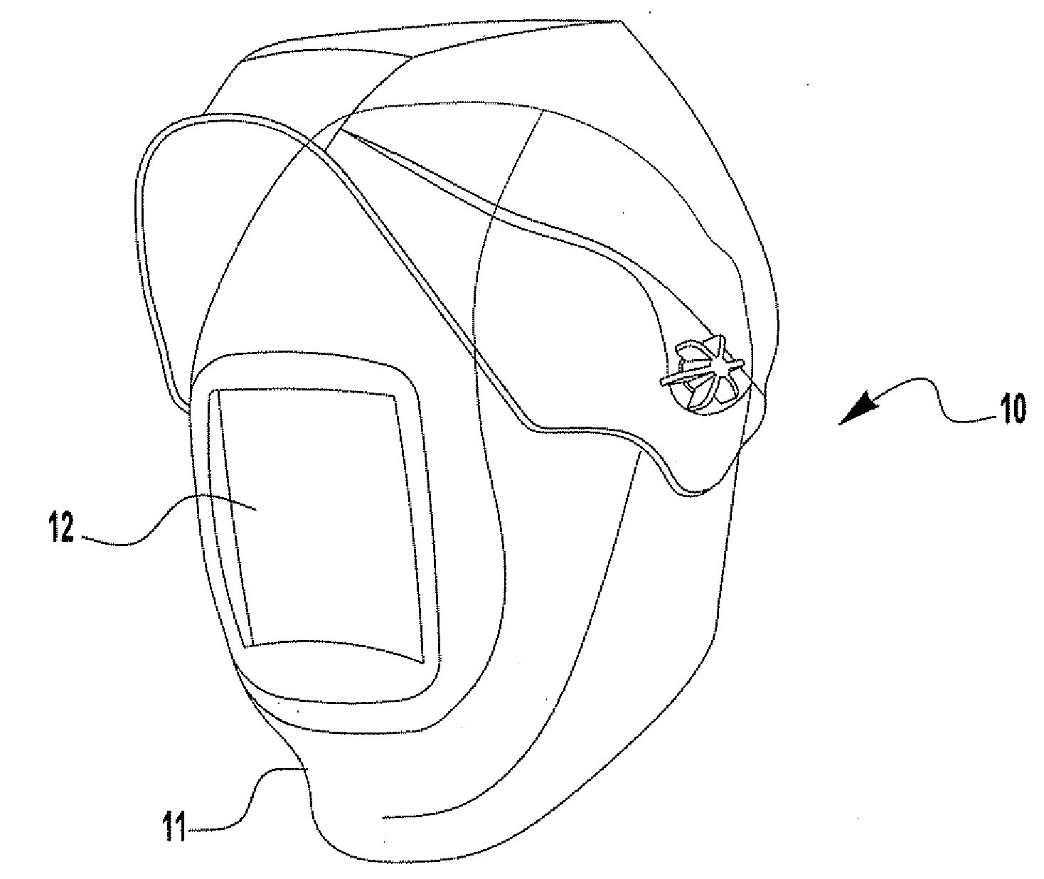
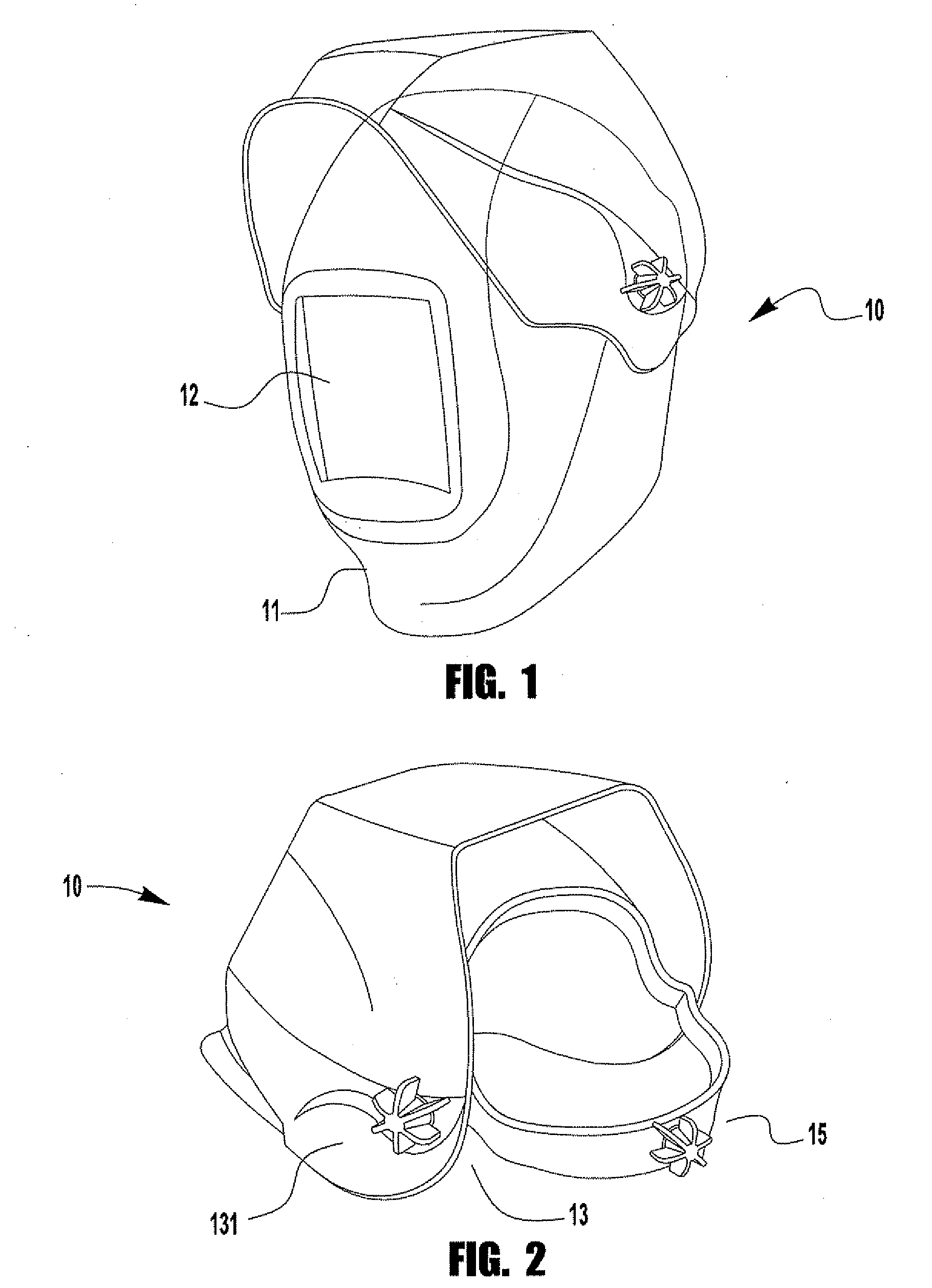
[0015]FIG. 1 depicts a diagrammatical representation of an exemplary embodiment of welding helmet 10 in the down position and in the up position. The down position is the position a welder would place the helmet 10 while welding. The up position is a position a welder would place the helmet 10 when the welder is not welding.

[0016]Although this invention is described with respect to welding helmets, the scope of the invention is not limited to welding helmets. The invention described herein can be applied to any type of protective helmet.

[0017]As can be seen in FIG. 1, welding helmet 10 includes a protective shell portion 11. Protective shell portion 11 is ...


PUM


Abstract

A protective helmet comprising having a protective shell, and a headgear mounted to the protective shell, wherein the headgear includes a tilt mechanism, the tilt mechanism comprising a tilt arm having a spring secured to the tilt arm, the spring having free portion disposed between a first portion and a second portion, the first portion and second portion being secured to the tilt arm and the free portion being free from the tilt arm.

Description

BACKGROUND OF THE INVENTION[0001]1. Field of the Invention[0002]Devices and apparatuses consistent with the present invention relate to tilt control mechanisms for protective helmets, including welding helmets.[0003]2. Description of the Related Art[0004]Welders often wear welding helmets with a protective darkened window to prevent injury to the welder's face and eyes during the welding operation. Such welding helmets often have tilt mechanisms that allow the welder to tilt the protective shell portion of the welding helmet between an up position, i.e., to place the protective shell portion so that it is no longer in front of the welder's face, allowing the welder a relatively unobstructed view of a workpiece, and a down position, i.e., the protective position.[0005]Conventional welding helmets have a problem in that conventional tilt mechanisms do not allow the welder to adjust the position of the protective shell portion of the welding helmet when tilted, i.e., the protective she...

Claims


Application Information

Patent Timeline
IPC IPC(8): A61F9/06A42B1/08
CPCA61F9/06A42B3/225
Inventor WANHAINEN, DANIEL J.
Owner LINCOLN GLOBAL INC
Why Eureka
Try Eureka