Tilt switch

a tilt switch and switch technology, applied in the direction of magnetic movement switch, contact, electrical apparatus, etc., can solve the problems of unreliability of tilt switch b>10/b>, the ball b>12/b> cannot easily roll away from the terminal,

Inactive Publication Date: 2010-09-30
HONG FU JIN PRECISION IND (SHENZHEN) CO LTD +1
View PDF9 Cites 4 Cited by
  • Summary
  • Abstract
  • Description
  • Claims
  • Application Information

AI Technical Summary

Problems solved by technology

However, the ball 12 will not easily roll away from the terminals 13 unless t...

Method used


Image

  • Tilt switch
  • Tilt switch
  • Tilt switch

Examples


Embodiment Construction

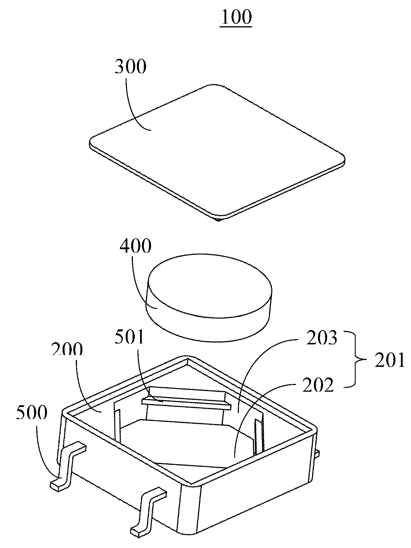
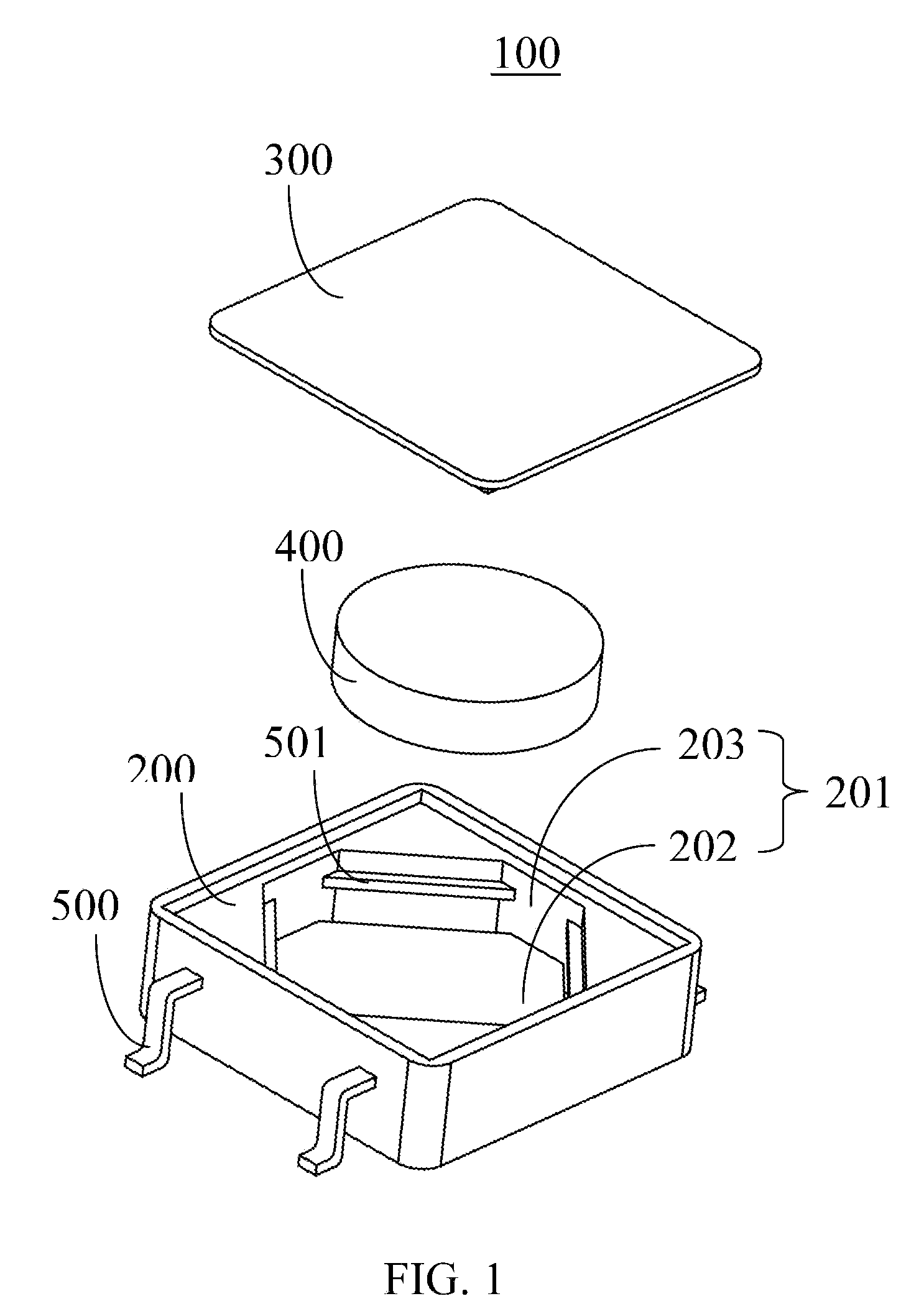
[0013]FIG. 1 shows a tilt switch 100 in accordance with an exemplary embodiment. The tilt switch 100 includes a housing 200, a cap 300, a conductive movable member 400, and a plurality of contact terminals 500.

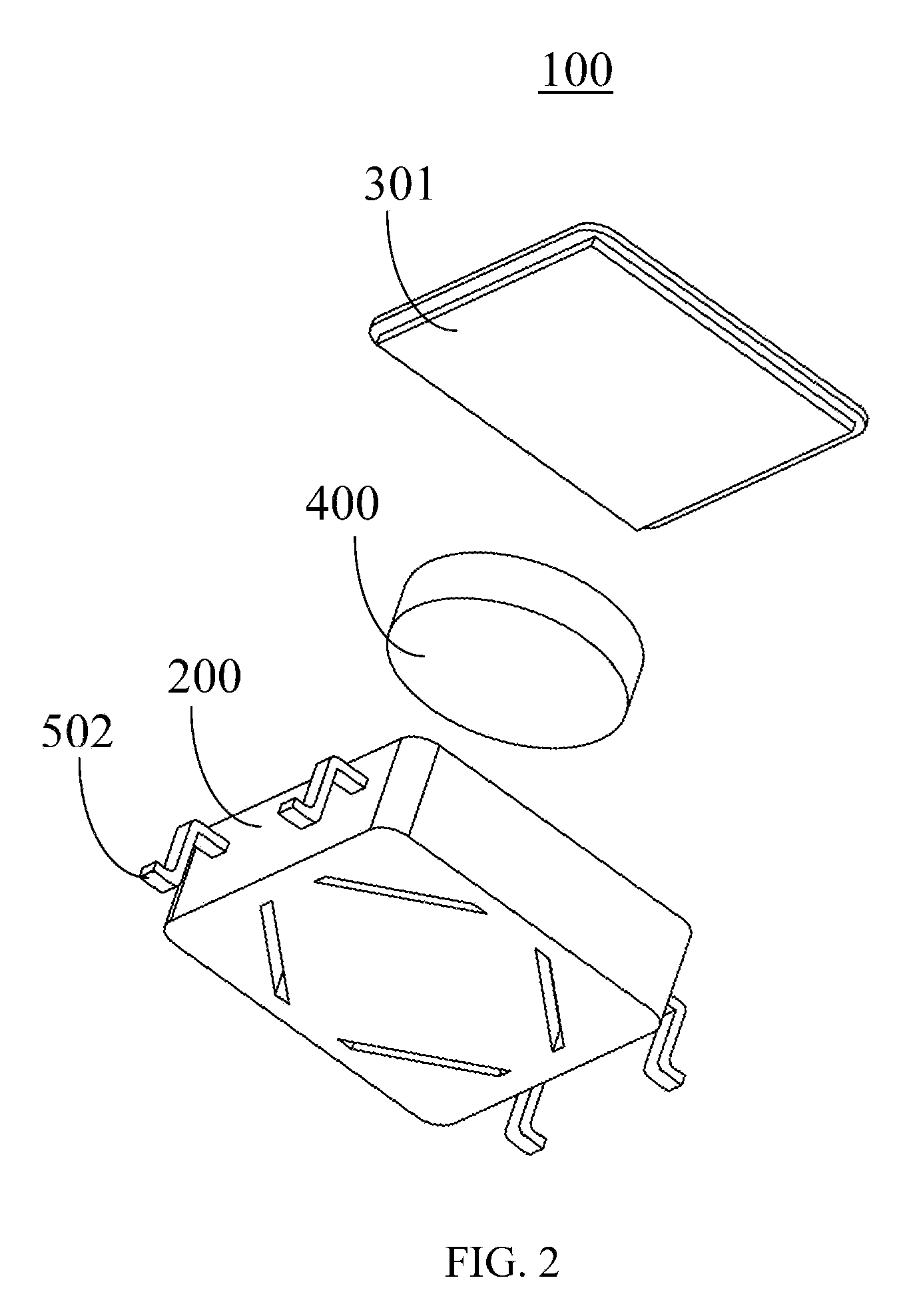
[0014]Referring to FIGS. 2 and 3, the housing 200 is made of electrically insulating material. In the exemplary embodiment, the housing 200 is made of plastic material. A chamber 201 is formed in the housing 200 and is defined by a bottom surface 202 and a surrounding wall 203. The cap 300 is attached above the chamber 201 and includes a bottom surface 301 that is opposite to the bottom surface 202. The cap 300 is shaped to fit the opening of the chamber 201 and is used to cover the chamber 201.

[0015]In the exemplary embodiment, there are four contact terminals 500. The four contact terminals 500 are formed integrally with the housing 200. The contact terminals 500 can be made of magnetic material. Each contact terminal 500 includes an inner terminal portion 501 and an outer t...


PUM


Abstract

A simulated eye is provided. The tilt switch comprises an electrically insulating housing with a chamber formed therein. The chamber is defined by a bottom surface and a surrounding surface. The tilt switch also includes a plurality of contact terminals, each of which comprises an inner terminal portion and an outer terminal portion. Each inner terminal portion protrudes out of the surrounding surface of the chamber and extends in a direction substantially parallel to the bottom surface. The tilt switch further includes an electrically conductive moving member placed in a space defined by the cap, the bottom surface, and the plurality of contact terminals. The electrically conductive moving member is capable of simultaneously contacting with at most two of the plurality of contact terminals.

Description

RELATED APPLICATIONS[0001]This application is related to U.S. patent application with an Attorney Docket Number of US23558 and a title of TILT SWITCH, which has the same assignee as the current application and has been concurrently filed.BACKGROUND[0002]1. Technical Field[0003]The present disclosure relates to tilt switches and, more particularly, to a tilt switch including a conductive movable member.[0004]2. Description of Related Art[0005]Referring to FIGS. 4 and 5, a tilt switch 10 is shown to include an insulating housing 11 with a chamber therein for rollably receiving an electrically conductive ball 12. Two pairs of first and second electric contact terminals 13 are press-fitted to a bottom plug 14, and have upper tip ends 131 extending into the chamber of the housing 11 when the plug 14 is secured to a bottom opening 111 of the housing 11 by virtue of engagement between protrusions 112 and recesses 142. Lower tip ends 132 of the terminals 13 are soldered to an electric conta...

Claims


Application Information

Patent Timeline
IPC IPC(8): H01H35/02
CPCH01H35/02H01H2036/0086H01H2001/5888H01H36/0073
Inventor CHU, MING-CHENGYANG, GUO-LINLUO, FENCHOU, CHENG-HAOJAN, TE-SHENG
Owner HONG FU JIN PRECISION IND (SHENZHEN) CO LTD
Why Eureka
Try Eureka