Developer supply container and developer supplying system

a technology of developer supply and supply container, which is applied in the direction of electrographic process equipment, instruments, optics, etc., can solve the problems of reducing the amount of toner supplied into the image forming apparatus, affecting the distribution of toner, so as to achieve suppressed developer scattering and high distribution property

Inactive Publication Date: 2010-11-04
CANON KK
View PDF22 Cites 48 Cited by
  • Summary
  • Abstract
  • Description
  • Claims
  • Application Information

AI Technical Summary

Benefits of technology

[0008]It is a further object of the present invention to provide a developer supply container wherein a discharging property of the developer is high, and the developer scattering is suppressed.
[0009]It is a further object of the present invention to provide a developer supply container wherein a developer discharging property is improved while suppressing rotation of the developer supply container in a direction opposite a predetermined direction.
[0010]It is a further object of the present invention to provide a developer supplying system wherein the developer discharging property is improved while suppressing the developer scattering.

Problems solved by technology

Since the toner is very fine powder, the toner may scatter around if the handling in the toner supplying operation is not proper.
Therefore, the agitator has to rotate downwardly relative to the toner discharge opening which faces laterally, and the toner feeding performance and toner discharging property is likely to deteriorate.
As a result, the amount of the toner supplied into the image forming apparatus decreases, and insufficient image density occurs, and / or the amount of the unusably remaining toner in the toner supply container is large.

Method used


Image

  • Developer supply container and developer supplying system
  • Developer supply container and developer supplying system
  • Developer supply container and developer supplying system

Examples


embodiment 1

Image Forming Apparatus

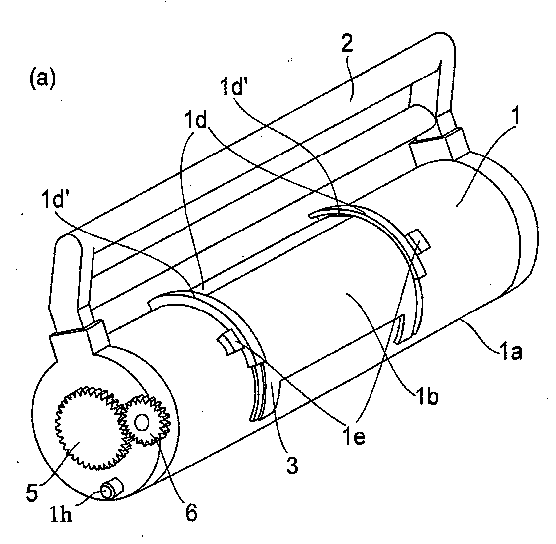
[0049]A toner supply container of Embodiment 1 (so-called toner cartridge) is loaded into a toner receiving apparatus of an image forming apparatus which is a copying machine of an electrophotographic type in the embodiment.

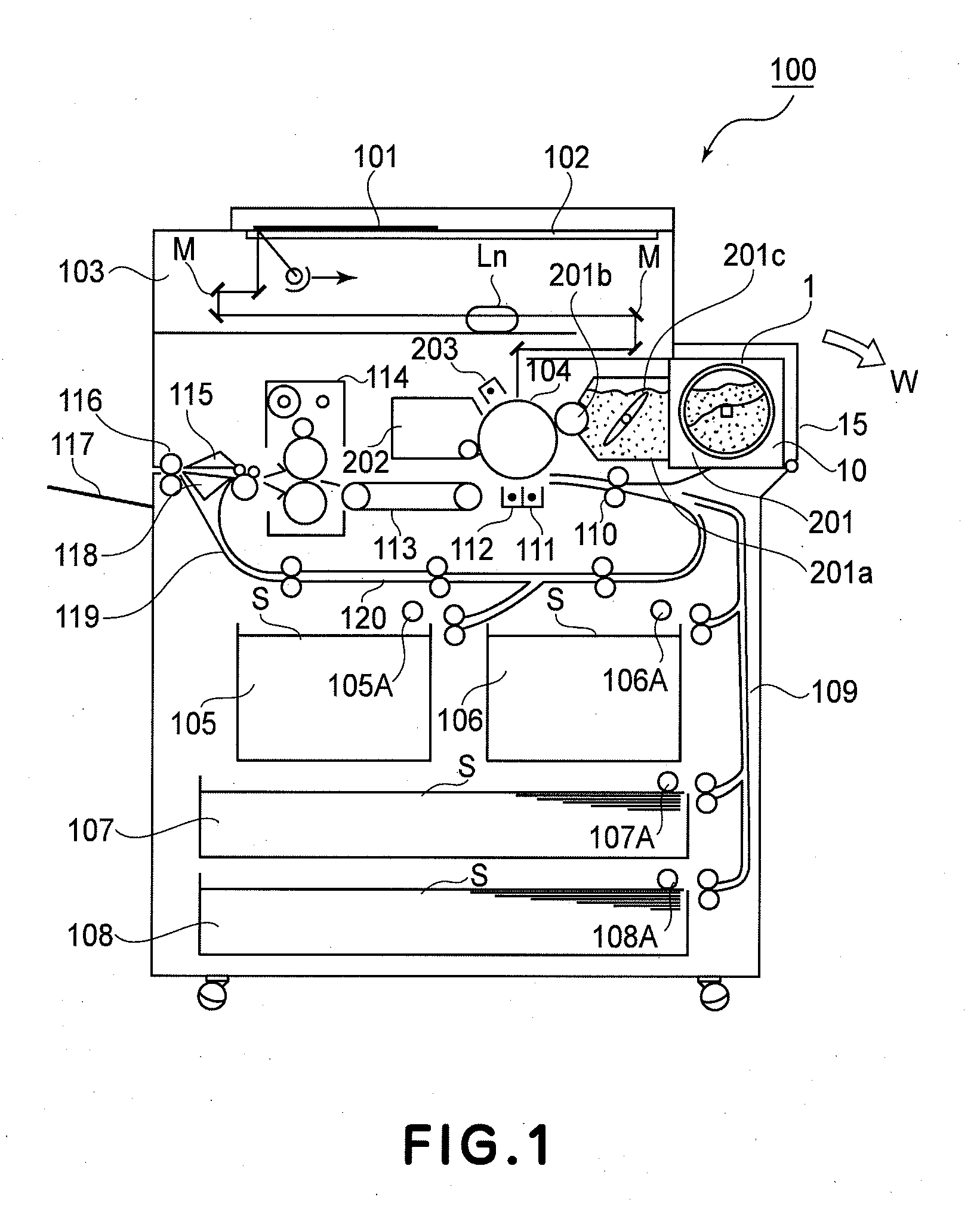
[0050]FIG. 1 illustrates such a copying machine.

[0051]In this Figure, designated by 100 is a main assembly of the electrophotographic copying machine. Designated by 101 is an original placed on an original supporting platen glass 102. A light image indicative of image information is projected on an image bearing member in the form of an electrophotographic photosensitive drum 104 through mirrors M and a lens Ln of an optical portion 103. Designated by reference numerals 105-108 are sheet cassettes. A proper sheet is selected from sheet size information of the cassettes 105-108, correspondingly to the sheet size of the original 101 or to the information inputted by the user at the operating portion, and proper sheet is picked up from one of ...

embodiment 2

[0205]Referring to FIG. 14, a toner supply container 1 according to Embodiment 2 will be described. The basic structures of the container are the same as the embodiment, and therefore, the description of the detail structures thereof is omitted for the sake of simplicity.

[0206]In Embodiment 1, the interrelating portion of the toner supply container uses the opening projection and the sealing projection. In Embodiment 2, a snap fit type engagement is used. In Embodiment 1, the toner supply container is mounted substantially in the direction perpendicular to the longitudinal direction of the toner supply container. In Embodiment 2, however, the toner supply container is mounted to the toner receiving apparatus substantially in the longitudinal direction of the toner supply container.

[0207]This is the main difference of the toner supply container from that of Embodiment 1. In the Figures, the same reference numerals as in Embodiment 1 are assigned to the element having a corresponding ...

embodiment 3

[0257]Referring to FIGS. 22 and 23, Embodiment 3 will be described. The basic structures of this embodiment are the same as Embodiments 1 and 2, and therefore, the detailed description of the common parts are omitted. In the Figures, the same reference numerals as in Embodiments 1 and 2 are assigned to the element having a corresponding function. In FIG. 22, (a) is a perspective view of the entirety of the toner supply container, and (b) is a perspective view of an inner cylinder. In FIG. 23, (a) shows the state when an outer cylinder is at a mount position, and (b) shows the state when the outer cylinder is at a set position, and (c) shows the state when the outer cylinder is at a supplying position.

[0258]In the Embodiments 1 and 2, the container body 1a containing the toner is rotated, but in the present embodiment, a portion not functioning as the toner accommodating portion is rotated.

[0259]As shown in FIG. 22, the toner supply container comprises an inner cylinder 800 containin...


PUM


Abstract

A developer supply container detachably mountable to a developer receiving apparatus and settable in a developer receiving apparatus by a setting operation including at least a rotation toward a setting position, includes a containing portion for containing the developer; a rotatable discharging member for discharging the developer out of said containing portion; drive transmitting means, engageable with a driving gear provided in said developer receiving apparatus and rotatable in a direction opposite the setting direction, for transmitting a rotating force from said driving gear to said discharging member.

Description

FIELD OF THE INVENTION AND RELATED ART[0001]The present invention relates to a developer container for supplying a developer to a developer receiving apparatus and a developer supplying system comprising the developer receiving apparatus and the developer supply container. Such a developer receiving apparatus is usable with a copying machine, a facsimile, a printer or other image forming apparatuses, and an image forming unit detachably mountable to the image forming apparatus.[0002]Conventionally, toner in the form of fine powder is used as a developer for image formation in the image forming apparatus such as an electrophotographic copying machine, a printer or the like. It is also conventional that toner is supplied from a toner supply container exchangeably set in the image forming apparatus with consumption of the toner in the image forming apparatus.[0003]Since the toner is very fine powder, the toner may scatter around if the handling in the toner supplying operation is not p...

Claims


Application Information

Patent Timeline
Patent Type & Authority Applications(United States)
IPC IPC(8): G03G15/08
CPCG03G15/0865G03G15/0877G03G15/087G03G15/0872G03G15/0887G03G2215/0802G03G15/00
Inventor NAGASHIMA, TOSHIAKIMURAKAMI, KATSUYAOKINO, AYATOMO
Owner CANON KK
Why Eureka
Try Eureka