Density Phase Separation Device

a separation device and density phase technology, applied in separation processes, laboratory glassware, instruments, etc., can solve the problems of special manufacturing equipment, adverse chemical reaction with the gel interface, limited shelf life of the gel-based separator product,

Active Publication Date: 2010-11-18
BECTON DICKINSON & CO
View PDF107 Cites 56 Cited by
  • Summary
  • Abstract
  • Description
  • Claims
  • Application Information

AI Technical Summary

Benefits of technology

[0034]The assembly of the present invention is advantageous over existing separation products that utilize separation gel. In particular, the assembly of the present invention will not interfere with analytes, whereas many gels interact with bodily fluids and / or analytes present within a collection container. The assembly of the present invention is also advantageous over existing mechanical separators in that the separator does not require piercing of the separator body to introduce a specimen into the collection container thereby minimizing pre-launch and sample pooling under the closure. The structure of the present mechanical separator also minimizes the loss of trapped fluid phases, such as serum and plasma within the separator body. Additionally, the assembly of the present invention does not require complicated extrusion techniques during fabrication, and may optimally employ two-shot molding techniques.

Problems solved by technology

However, current polyester gel serum separation tubes require special manufacturing equipment to both prepare the gel and fill the tubes.
Moreover, the shelf-life of the gel-based separator product is limited.
Accordingly, if certain drugs are present in the blood sample when it is taken, an adverse chemical reaction with the gel interface can occur.
Furthermore, if an instrument probe is inserted too deeply into a collection container, then the instrument probe may become clogged if it contacts the gel.
This can result in sample pooling under the closure, device pre-launch in which the mechanical separator prematurely releases during blood collection, trapping of a significant quantity of fluid phases, such as serum and plasma, poor sample quality, and / or barrier failure under certain circumstances.
Furthermore, previous mechanical separators are costly and complicated to manufacture due to the complicated multi-part fabrication techniques.

Method used


Image

  • Density Phase Separation Device
  • Density Phase Separation Device
  • Density Phase Separation Device

Examples


Embodiment Construction

[0131]For purposes of the description hereinafter, the words “upper”, “lower”, “right”, “left”, “vertical”, “horizontal”, “top”, “bottom”, “lateral”, “longitudinal”, and like spatial terms, if used, shall relate to the described embodiments as oriented in the drawing figures. However, it is to be understood that many alternative variations and embodiments may be assumed except where expressly specified to the contrary. It is also to be understood that the specific devices and embodiments illustrated in the accompanying drawings and described herein are simply exemplary embodiments of the invention.

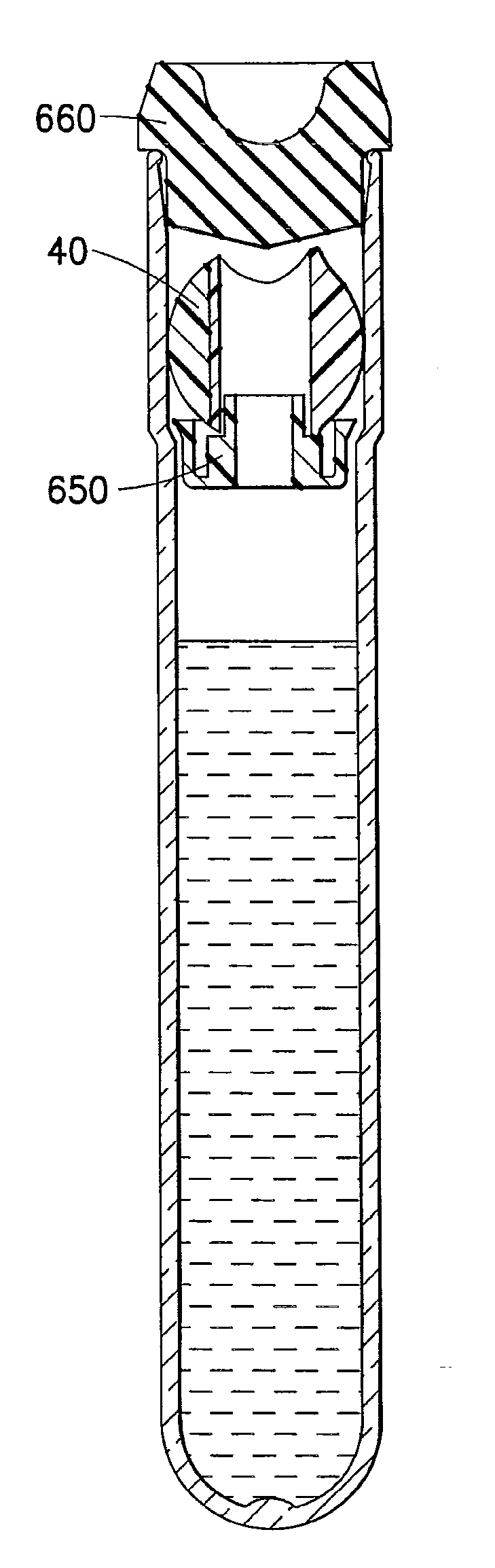
[0132]The mechanical separator of the present invention is intended for use with a collection container for providing separation of a sample into higher and lower density phase components, as will be discussed herein. For example, the present mechanical separator can be used to provide a separation of serum or plasma from whole blood through the use of differential buoyancy to cause a seal...


PUM

PropertyMeasurementUnit
densityaaaaaaaaaa
densityaaaaaaaaaa
densityaaaaaaaaaa

Abstract

A mechanical separator for separating a fluid sample into first and second phases within a collection container is disclosed. The mechanical separator may have a separator body having a through-hole defined therein, with the through-hole adapted for allowing fluid to pass therethrough. The separator body includes a float, having a first density, and a ballast, having a second density greater than the first density. A portion of the float is connected to a portion of the ballast. Optionally, the float may include a first extended tab adjacent a first opening of the through-hole and a second extended tab adjacent the second opening of the through-hole. In certain configurations, the separator body also includes an extended tab band disposed about an outer surface of the float. The separator body may also include an engagement band circumferentially disposed about at least a portion of the separator body.

Description

CROSS REFERENCE TO RELATED APPLICATIONS[0001]This application claims priority to U.S. Provisional Patent Application Ser. No. 61 / 178,599 filed May 15, 2009, the entire disclosure of which is hereby incorporated by reference.BACKGROUND OF THE INVENTION[0002]1. Field of the Invention[0003]The subject invention relates to a device for separating higher and lower density fractions of a fluid sample. More particularly, this invention relates to a device for collecting and transporting fluid samples whereby the device and fluid sample are subjected to centrifugation in order to cause separation of the higher density fraction from the lower density fraction of the fluid sample.[0004]2. Description of Related Art[0005]Diagnostic tests may require separation of a patient's whole blood sample into components, such as serum or plasma (the lower density phase components), and red blood cells (the higher density phase components). Samples of whole blood are typically collected by venipuncture th...

Claims


Application Information

Patent Timeline
Patent Type & Authority Applications(United States)
IPC IPC(8): B01D17/032B01D17/028
CPCB01L3/50215B01D21/262G01N33/491Y10T436/25375B01D17/0217G01N1/34B01D21/2405B01D17/12B01D17/02A61B5/15G01N33/49G01N1/18G01N33/48A61B5/157B01L3/5021G01N1/4077G01N2001/4083
Inventor CRAWFORD, JAMIESON W.ATTRI, RAVIBATTLES, CHRISTOPHER A.BARTFELD, BENJAMIN R.HIRES, GREGORY R.
Owner BECTON DICKINSON & CO
Why Eureka
Try Eureka