Conveyor belt or treadmill belt

a technology of conveyor belts and treadmill belts, applied in the direction of gymnastic exercise, weaving, sport apparatus, etc., can solve the problems of poor stepping stress, easy peeling of conveyor belts or treadmill belts, etc., and achieve the effect of preferred stepping comfor

Inactive Publication Date: 2010-12-02
WANG SHUEI MU
View PDF8 Cites 8 Cited by
  • Summary
  • Abstract
  • Description
  • Claims
  • Application Information

AI Technical Summary

Benefits of technology

[0011]The primary object of the present invention is to provide a conveyor belt or treadmill belt that can dispose a shock absorbing structure in the laminating layer to obtain a preferred stepping comfortness.

Problems solved by technology

However, such a conventional conveyor belt or treadmill belt is easy to be peeled off and has poor stepping stress.

Method used


Image

  • Conveyor belt or treadmill belt
  • Conveyor belt or treadmill belt
  • Conveyor belt or treadmill belt

Examples


first embodiment

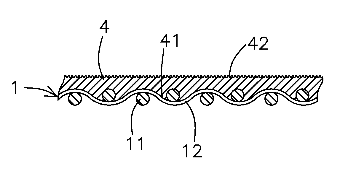
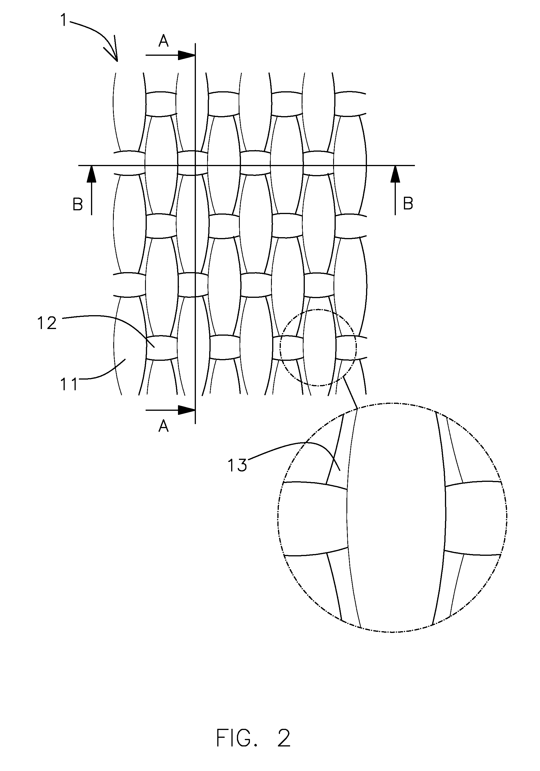
[0028]Referring to FIGS. 5 and 6, a conveyor belt or treadmill belt in accordance with the present invention at least comprises: a cloth layer 1 woven by at least one warp 11 and woof 12 and having an outer surface and an inner surface in response to each other, a clearance passing through the inner and the outer surfaces and being formed between the warp 11 and the woof 12 of the cloth layer 1, wherein the warp 11 and the woof 12 can be formed from yarns with anti-static agent or the cloth layer 1 is soaked in the anti-static agent to obtain anti-static effect;

[0029]a laminating layer 4 serving as being stepped, the laminating layer 1 being molded to a laminated film and melted to couple with the outer surface of the cloth layer 1, such that the laminating layer 4 merges into the clearance between the warp 11 and the woof 12 of the cloth layer 1 so that the laminating layer 4 is integrally formed a rough connecting surface 41, the connecting surface 41 engaging with the clearance o...

second embodiment

[0031]Referring to FIG. 7, a conveyor belt or treadmill belt according to the present invention at lease comprises:

[0032]a cloth layer 1 woven by at least one warp 11 and woof 12, each warp 11 and woof 12 having an outer surface and an inner surface in response to each other, a clearance passing through the inner and the outer surfaces and being formed between the warp 11 and the woof 12;

[0033]a laminating layer 4 serving as being stepped, the laminating layer 1 being molded to a laminated film and melted to couple with an outer surface of the cloth layer 1, such that the laminating layer 4 merges into the clearance between the warp 11 and the woof 12 of the cloth layer 1 so that the laminating layer 4 is integrally formed a rough connecting surface 41;

[0034]a gel layer 5 coated on an inner surface of the cloth layer 1 so as to link with the connecting surface 41 of the laminating layer 4, thus engaging the cloth layer 1 between the gel layer 5 and the laminating layer 4. The gel la...


PUM

PropertyMeasurementUnit
frequencyaaaaaaaaaa
stepping stressaaaaaaaaaa
anti-peel strengthaaaaaaaaaa

Abstract

A conveyor belt or treadmill belt comprises a cloth layer woven by at least one warp and woof and having an outer surface and an inner surface in response to each other, a clearance passing through the inner and the outer surfaces and being formed between the warp and the woof; a laminating layer serving as being stepped, the laminating layer being molded to a laminated film and melted to couple with an outer surface of the cloth layer, such that the laminating layer merges into the clearance between the warp and the woof of the cloth layer so that the laminating layer is integrally formed a rough connecting surface; a gel layer coated on an inner surface of the cloth layer so as to link with the connecting surface of the laminating layer, thus engaging the cloth layer between the gel layer and the laminating layer.

Description

BACKGROUND OF THE INVENTION[0001]1. Field of the Invention[0002]The present invention relates to a conveyor belt or treadmill belt that can dispose a shock absorbing structure in the laminating layer to obtain a preferred stepping comfortness.[0003]2. Description of the Prior Art[0004]Referring to FIG. 1, a conventional conveyor belt or treadmill belt are coupled together in high frequency manner so that the conveyor belt or treadmill belt can be fixed on front and rear transmission wheels (not shown) respectively, obtaining conveying or stepping function.[0005]As shown in FIGS. 2-4, the conventional conveyor belt or treadmill belt at least comprises:[0006]a cloth layer 1 woven by at least one warp 11 and woof 12, a clearance 13 being formed between the warp 11 and woof 12, an inner surface of the cloth layer 1 being fixed around outer sides of two transmission wheels;[0007]an adhesive layer 2 serving as coating adhesive agent onto an outer side of the cloth layer 1 by using a gel c...

Claims


Application Information

Patent Timeline
Patent Type & Authority Applications(United States)
IPC IPC(8): A63B22/02B32B27/12B32B27/14
CPCA63B22/02A63B22/0285B32B27/12Y10T442/3919Y10T442/3854A63B22/0207B32B5/024B32B7/12B32B27/18B32B3/30B32B2255/02B32B2260/021B32B2264/101B32B2307/21B32B2307/50B32B2307/538B32B2307/54B32B2307/56B32B2307/718B32B2307/744B32B2433/02Y10T428/2481
Inventor WANG, SHUEI MU
Owner WANG SHUEI MU
Why Eureka
Try Eureka