Projector

a projector and projection surface technology, applied in the field of projectors, can solve the problems of difficult operation the projected image is blocked, and the projection image displayed on the projection surface cannot be maintained in a good condition, so as to increase the length dimension and easily dispose of the plurality of operation buttons

Active Publication Date: 2010-12-23
SEIKO EPSON CORP
View PDF12 Cites 10 Cited by
  • Summary
  • Abstract
  • Description
  • Claims
  • Application Information

AI Technical Summary

Benefits of technology

[0022]According to the aspect of the invention, the concave portion is formed in the second tilted surface of the first sidewall, and the image opening is formed in the bottom of the concave portion. Because of this, it is possible to, while setting the formation position of the image opening to the position spaced the predetermined distance from the reflecting mirror, to set the second tilted surface to a position shifted, by an amount equivalent to the length of the sidewall of the concave portion, from the reflecting mirror to the optical path downstream side of the projected image. That is, by setting the second tilted surface to the heretofore described position, it is possible to increase the length dimension of the disposition surface (the length dimension from the region meeting the second tilted surface to the end of the projection optical device far from the projection surface) in comparison with the heretofore described configuration wherein the concave portion is not formed in the second tilted surface.
[0023]Consequently, it is possible to easily dispose the plurality of operation buttons on the disposition surface.

Problems solved by technology

However, as the projector, a configuration is in heavy usage wherein a plurality of operation buttons for prompting a user to operate and implement a starting, and the like, of the projector are exposed to the outside of the exterior housing.
However, when the plurality of operation buttons are disposed in the first disposition position, there is a problem in that the projected image is blocked by the user's hand, or the like, when the plurality of operation buttons are operated, and a projection image displayed on the projection surface cannot be maintained in a good condition.
However, there is a problem in that it is difficult to operate the plurality of operation buttons in comparison with when the plurality of operation buttons are disposed in the first disposition position.
That is, it is difficult to dispose the plurality of operation buttons on the disposition surface.

Method used


Image

  • Projector
  • Projector
  • Projector

Examples


Embodiment Construction

[0031]Hereafter, a description will be given, based on the drawings, of one embodiment of the invention.

Configuration of Projector

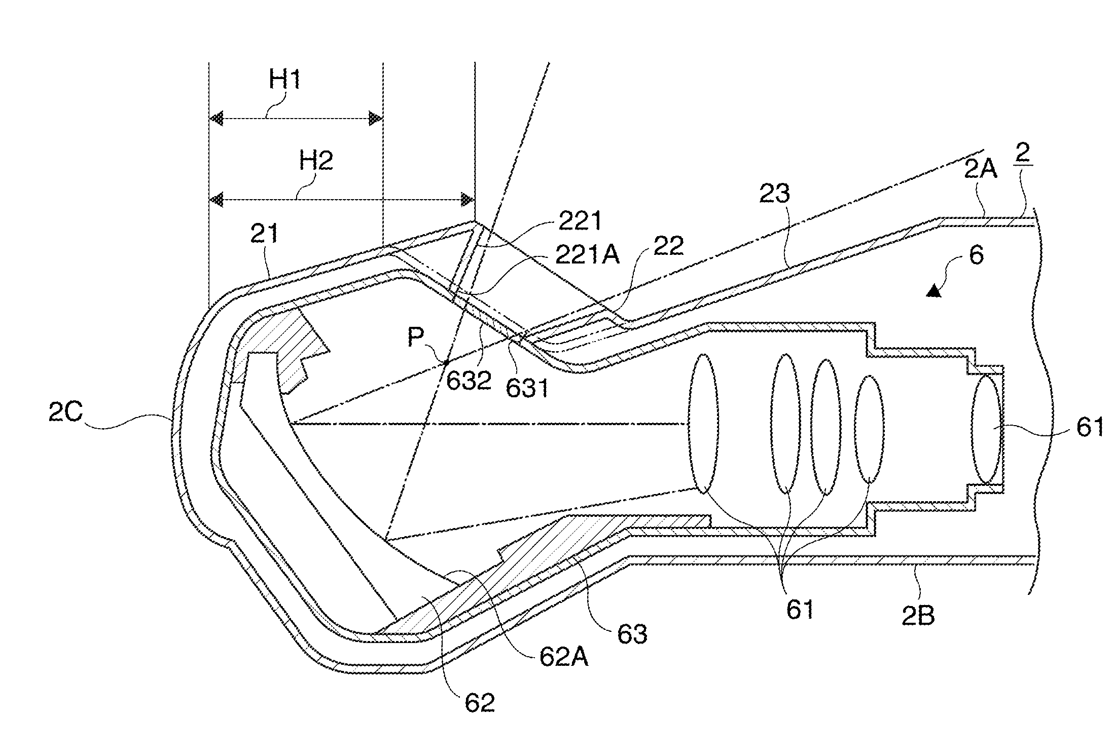
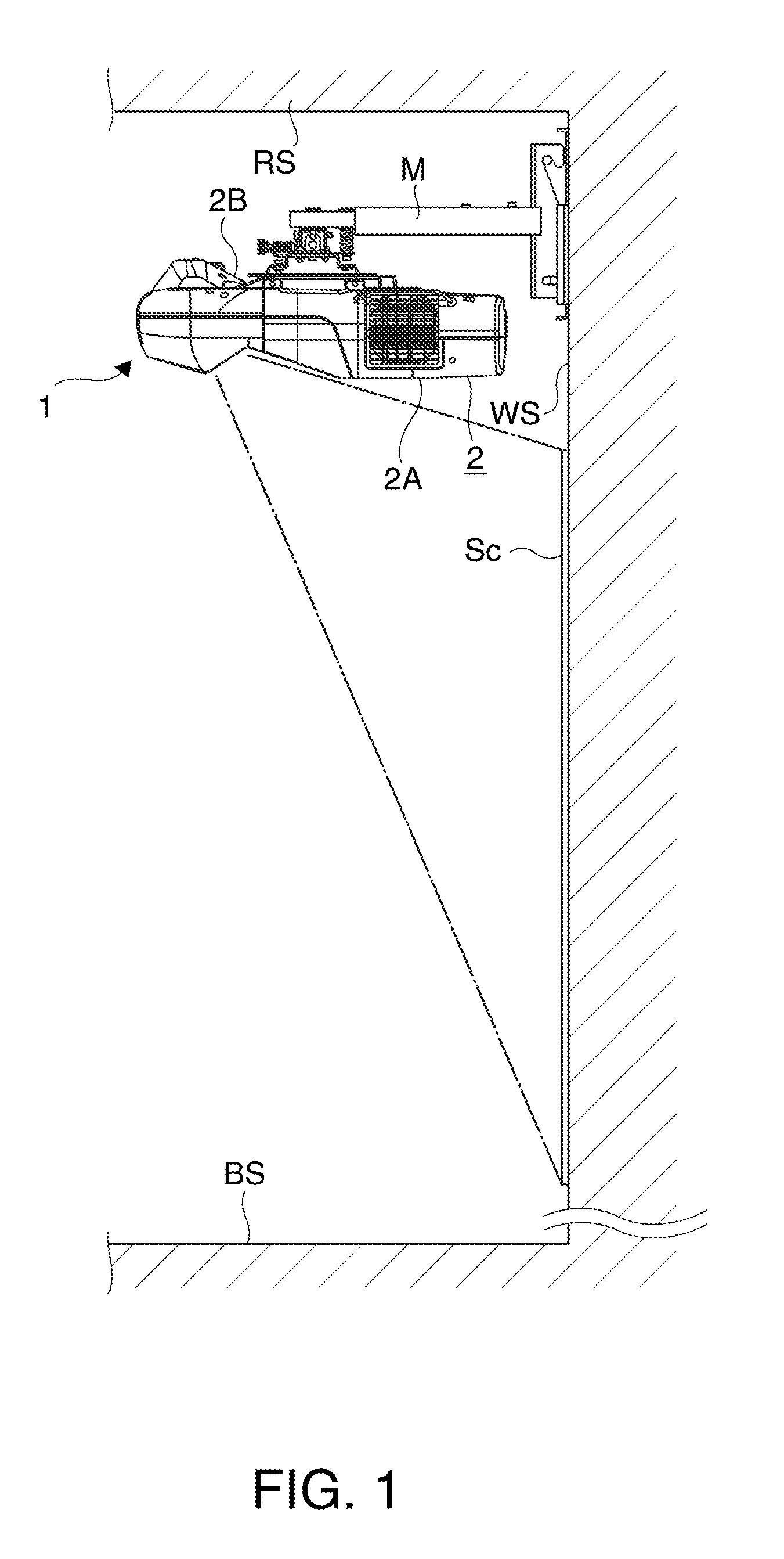
[0032]FIG. 1 is a side view of a projector 1 in a used condition.

[0033]The projector 1 forms an image in accordance with image information, and projects the formed image onto a projection surface Sc (FIG. 1) such as a screen.

[0034]In the embodiment, as shown in FIG. 1, the projector 1 is disposed in a position near a ceiling surface RS, suspended with a ceiling mount M, in a room in which the projector 1 is installed. Then, the projector 1 projects the image toward the projection surface Sc installed on a wall surface WS.

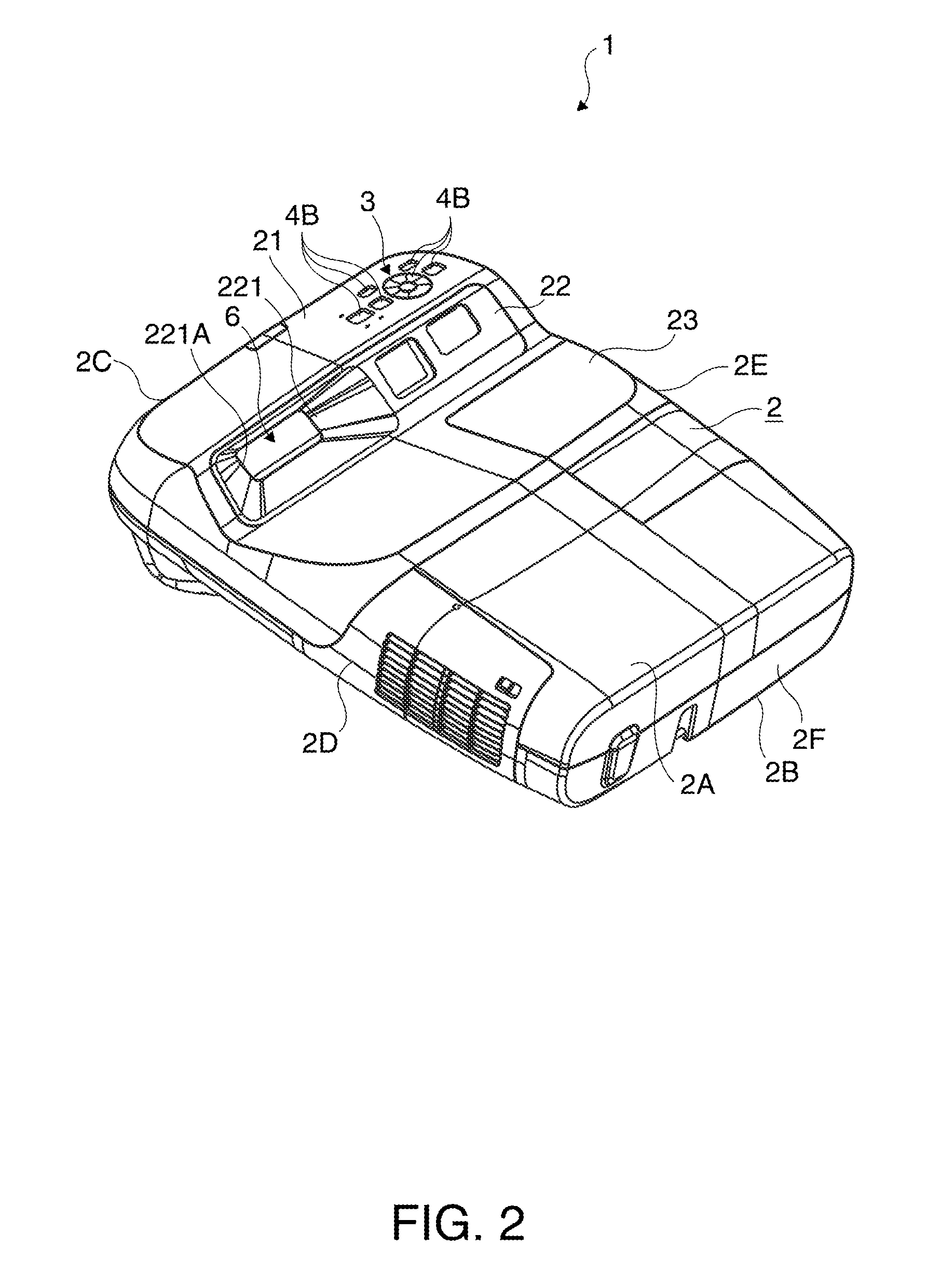
[0035]The projector 1 includes an exterior housing 2 configuring its exterior, as shown in FIG. 1.

[0036]Hereafter, for convenience of description, of a pair of sidewalls 2A and 2B of the exterior housing 2 which intersect in a vertical direction, the sidewall 2A facing a floor surface BS in the used condition shown in FIG. 1 will be taken...


PUM


Abstract

A projector includes: an exterior housing configuring an exterior; a projection optical device which projects an image toward a projection surface; and a plurality of operation buttons which, being disposed in such a way as to be exposed to the outside of the exterior housing, an image opening for allowing the image projected from the projection optical device to pass through is formed in one sidewall, among sidewalls configuring the exterior housing, which intersects in a vertical direction, the projection optical device includes a reflecting mirror which reflects the image, and projects it through the image opening, and the plurality of operation buttons are disposed on a side of the one sidewall farther from the projection surface than the image opening.

Description

BACKGROUND[0001]1. Technical Field[0002]The present invention relates to a projector.[0003]2. Related Art[0004]To date, as a front projection type projector, a configuration has been known wherein a short focal projection optical device whose projection distance is shortened is employed in order to improve a degree of freedom in installing the projector (for example, refer to JP-A-2007-334052).[0005]In the projector described in JP-A-2007-334052, the projection optical device includes at an optical path downstream extremity an aspherical mirror having a reflecting surface of a free-form surface shape which is not rotationally symmetric. Then, by an image being reflected by the aspherical mirror, the angle of the image is widened through an image opening provided in a top surface, among sidewalls configuring an exterior housing, which intersects in a vertical direction. With this kind of configuration, it is possible to install the projector in a position near a projection surface su...

Claims


Application Information

Patent Timeline
Patent Type & Authority Applications(United States)
IPC IPC(8): G03B21/28
CPCG03B21/28G03B21/14G03B21/147H04N9/3141
Inventor OTSUKI, NOBUYUKINAKAYAMA, TETSUKAWABE, GENTA
Owner SEIKO EPSON CORP
Why Eureka
Try Eureka