Walking-type working machine

A working machine and walking-type technology, which is applied to farming machines, agricultural machinery and tools, agriculture, etc., and can solve problems such as obstacles in the storage part of the gas tank

Inactive Publication Date: 2011-04-13
HONDA MOTOR CO LTD
View PDF2 Cites 0 Cited by
  • Summary
  • Abstract
  • Description
  • Claims
  • Application Information

AI Technical Summary

Problems solved by technology

[0005] Therefore, when attaching the carrying handle to the handle support of the

Method used


Image

  • Walking-type working machine
  • Walking-type working machine
  • Walking-type working machine

Examples


Embodiment Construction

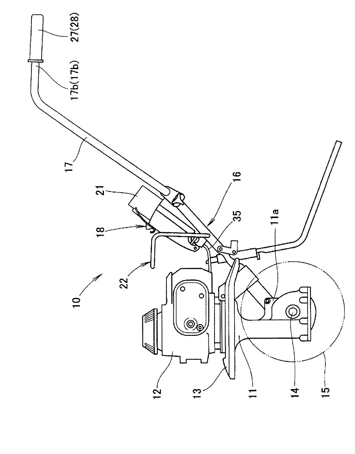
[0028] In this embodiment, a walking type rotary cultivator is shown as an example of a walking type working machine, but the walking type working machine is not limited to this.

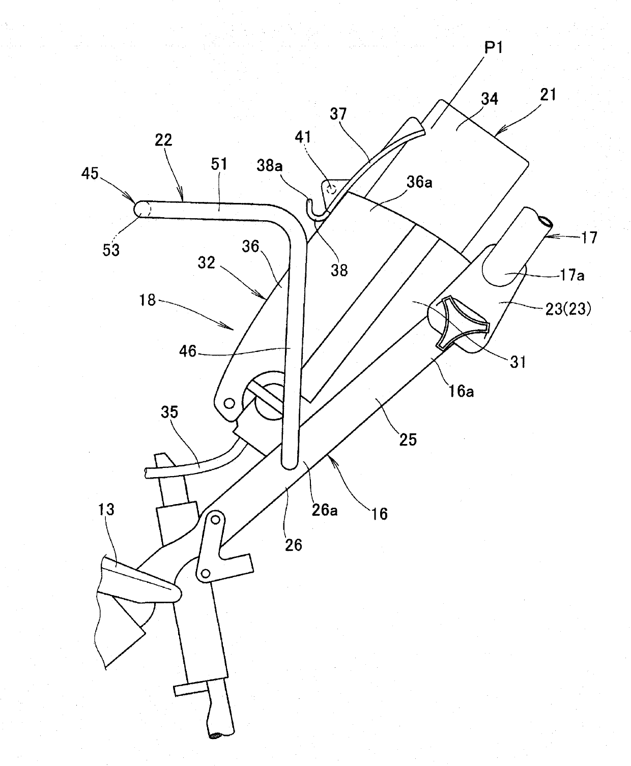
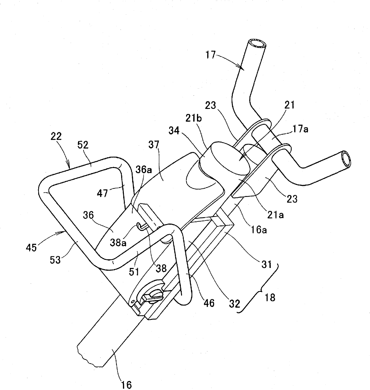
[0029] figure 1 The illustrated walk-behind working machine 10 includes: a gas engine 12 mounted on the upper end of a rotary cultivator main body (working machine main body) 11; Below; a plurality of rotary tiller claws 15, these rotary tiller claws 15 are arranged below the fender 13 via the rotary tiller shaft 14; handle pillar 16, the handle pillar 16 is arranged on the rear part 11a of the rotary tiller main body 11; the operating handle 17, the operating handle 17 is arranged on the handle pillar 16; the gas tank storage part (gas tank holding part) 18, the gas tank storage part 18 is arranged on the handle pillar 16; the box-type gas tank 21, the box-type gas tank 21 is accommodated on the gas tank storage part 18;

[0030] This walk-behind operating machine 10 is a walk-behind rotary culti...


PUM


Abstract

A walking-type working machine in which a gas-container housing section (cassette-type gas container) and a carry handle are mounted to a handle post. The walking-type working machine (10) is provided with a cassette-type gas container (21) mounted to a handle post (16), which rises upward and rearward from a rear section (11a) of a working machine body (11), so as to be oriented in the longitudinal direction of the handle post. A gas engine (12) is driven by fuel in the cassette-type gas container (21). The walking-type working machine is provided with a carry handle (22) for carrying the machine. The carry handle (22) is mounted to the handle post and is formed so as to surround the cassette-type gas container. The carry handle has a grip (45).

Description

technical field [0001] The present invention relates to a walking type work machine that is provided with a cassette-type gas container in a direction along a handle post, and uses fuel in the cassette-type gas container to drive a gas engine. Background technique [0002] Among walking-type working machines, there is a walking-type working machine in which a handle strut rises rearward and upward from the rear of the working machine main body, and a carry handle extends upward from the upper portion of the outer peripheral wall of the handle strut. As disclosed in Patent Document 1, there is known a walking type working machine in which the walking type working machine can be lifted and transported by grasping the handle portion of the handle by hand. [0003] On the other hand, among walk-behind work machines, as disclosed in Patent Document 2, there is known a gas engine-mounted work machine in which a gas engine is mounted on a work machine main body, and a handle suppor...

Claims


Application Information

Patent Timeline
IPC IPC(8): A01B33/02A01B33/08B60K15/03B60K15/063
CPCF17C2270/0736B60Y2200/41F17C2205/0111A01B33/028A01B33/16F17C2223/0153B60K15/07F17C13/085F17C2221/035F17C2223/033F17C2205/0165
Inventor 小林秀明伊藤智树
Owner HONDA MOTOR CO LTD
Why Eureka
Try Eureka