
Method of Raising Oil Temperature at the Outlet of Oil Well and Structure of Oil Well

An outlet, oil well technology, applied in wellbore/well components, drilling equipment, earth-moving drilling, etc., can solve the problems of high energy consumption, complex wellhead equipment, etc., and achieve long service life, convenient manufacturing and installation, and simplified structure. Effect

Inactive Publication Date: 2015-12-02
NANJING UNIV OF TECH
View PDF6 Cites 0 Cited by
  • Summary
  • Abstract
  • Description
  • Claims
  • Application Information

AI Technical Summary

Problems solved by technology

[0006] The purpose of the present invention is to solve a series of problems such as complex wellhead equipment and high energy consumption that need to be kept in a suitable outlet temperature range by means of external heat supply or electric heating to increase fluidity in the current crude oil extraction process. Invent a method of increasing the oil temperature at the outlet of the oil well based on the heat pipe principle, and design a wellbore structure using the heat pipe as the oil pipe

Method used


Image

  • Method of Raising Oil Temperature at the Outlet of Oil Well and Structure of Oil Well

Examples


Embodiment 1

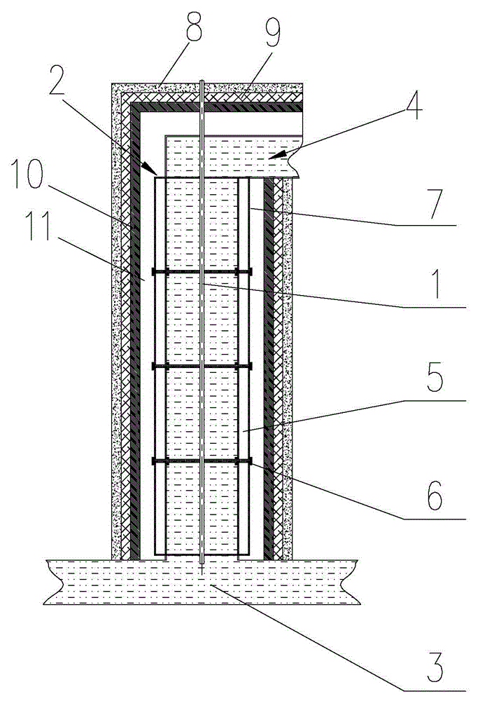
[0025] Such as figure 1 shown.

[0026] A method for increasing the oil temperature at the outlet of an oil well, the key of which is to connect several gravity-type casing-shaped heat pipes into one as an oil pipe, so that crude oil is drawn out of the oil-oil pipe through the center of each gravity-type casing-shaped heat pipe, The working medium is injected into the closed pipe wall gap of the gravity casing heat pipe and vacuumized. The lower part of each gravity casing is the evaporation section of the heat pipe, and the upper part is the condensation section of the heat pipe. , for each gravity-type sleeve-shaped heat pipe, the inner surface of the lower part is in the hot fluid area, and the inner surface of the upper part is in the cold fluid area. Since the heat pipe has the characteristic that it can work normally under a small temperature difference between the cold and hot fluids, and The heat of the lower hot crude oil can be transferred upwards to the upper cold...

Embodiment 2

[0033] Such as figure 1 shown.

[0034] An oil well structure that can increase the oil temperature at the outlet of the oil well, it includes a sucker rod 1 and an oil pipe 2, and the installation method and structure of the oil pipe 2 in the oil well are the same as the prior art, such as figure 1As shown, the entire oil well is composed of the outermost concrete layer 8, insulation layer 9 and casing 10, the insulation layer 9 is located between the concrete layer 8 and the casing 10, the oil pipe 2 is located in the casing 10, and the oil pipe 2 and the casing There is a gap 11 between 10, in the gap 11 there will be various debris (such as water, oil, soil, gravel, etc.) to form a layer of debris, the existence of the gap 11 is also convenient for the maintenance and replacement of the oil pipe 2, the sucker rod The upper end of 1 passes through the casing, insulation layer and concrete layer and moves up and down in the oil pipe 2 under the drive of the power device, so...


PUM


Abstract

The invention discloses a method for improving oil temperature at an outlet of an oil well and a corresponding oil well structure. The method for improving the oil temperature at the outlet of the oil well and the corresponding oil well structure are characterized in that a plurality of gravity-type sleeve-shaped heat pipes are connected into a whole and used as oil pipes so that crude oil passes through the centers of the gravity-type sleeve-shaped heat pipes and are pumped out of the oil well. Airtight spaces between pipe walls of the gravity-type sleeve-shaped heat pipes are filled with working media and are vacuumized. The lower portion of each gravity-type sleeve-shaped heat pipe is a heat pipe evaporation segment, and the upper portion of each gravity-type sleeve-shaped heat pipe is a heat pipe condensation segment. Heat passing through the bottom ends of the gravity-type sleeve-shaped heat pipes is uploaded step by step, and then the crude oil passing through the centers of the gravity-type sleeve-shaped heat pipes continuously carries out heat exchange with pipe walls so that the viscosity of the crude oil can be reduced and the crude oil can not become thick. Consequently, the temperature of the crude oil in the gravity-type sleeve-shaped heat pipes nearest to oil outlets can meet the requirement for the thickening-preventing oil outlet temperature. The method for improving the oil temperature at the outlet of the oil well and the corresponding oil well structure have the advantages of being energy-saving, simple, easy to realize and capable of substantially reducing oil extraction cost.

Description

technical field [0001] The present invention relates to an oil production method and an oil pipe structure, in particular to a method for recovering relatively deep underground high-temperature crude oil heat and pumping it to the wellhead during the oil pumping process of heavy oil wells to improve the fluidity of pumped crude oil, especially heavy oil and oil well structure. Specifically, it is a kind of electric heating device and its control device that can reduce the power consumption of heavy oil wells, and even remove the entire sucker rod, or inject high-temperature and high-pressure steam into the oil well, so that the pumping operation of the pumping system becomes easier. Simple, improving the fluidity of crude oil, reducing the accident rate of oil pumping and improving the oil temperature at the outlet of the oil well and the structure of the oil well. Background technique [0002] As we all know, during the crude oil extraction process of heavy oil wells, elec...

Claims


Application Information

Patent Timeline
Patent Type & Authority Patents(China)
IPC IPC(8): E21B36/00E21B43/24E21B17/00
Inventor 王良虎李菊香
Owner NANJING UNIV OF TECH
Learn More