
Multi-chip package and method of providing die-to-die interconnects in same

Active Publication Date: 2010-12-30
INTEL CORP
View PDF9 Cites 167 Cited by
  • Summary
  • Abstract
  • Description
  • Claims
  • Application Information

AI Technical Summary

Problems solved by technology

The interconnect density is an important consideration because an insufficient number of die connections would limit the

Method used


Image

  • Multi-chip package and method of providing die-to-die interconnects in same
  • Multi-chip package and method of providing die-to-die interconnects in same
  • Multi-chip package and method of providing die-to-die interconnects in same

Examples


Example

[0017]For simplicity and clarity of illustration, the drawing figures illustrate the general manner of construction, and descriptions and details of well-known features and techniques may be omitted to avoid unnecessarily obscuring the discussion of the described embodiments of the invention. Additionally, elements in the drawing figures are not necessarily drawn to scale. For example, the dimensions of some of the elements in the figures may be exaggerated relative to other elements to help improve understanding of embodiments of the present invention. The same reference numerals in different figures denote the same elements, while similar reference numerals may, but do not necessarily, denote similar elements.

[0018]The terms “first,”“second,”“third,”“fourth,” and the like in the description and in the claims, if any, are used for distinguishing between similar elements and not necessarily for describing a particular sequential or chronological order. It is to be understood that th...


PUM


Abstract

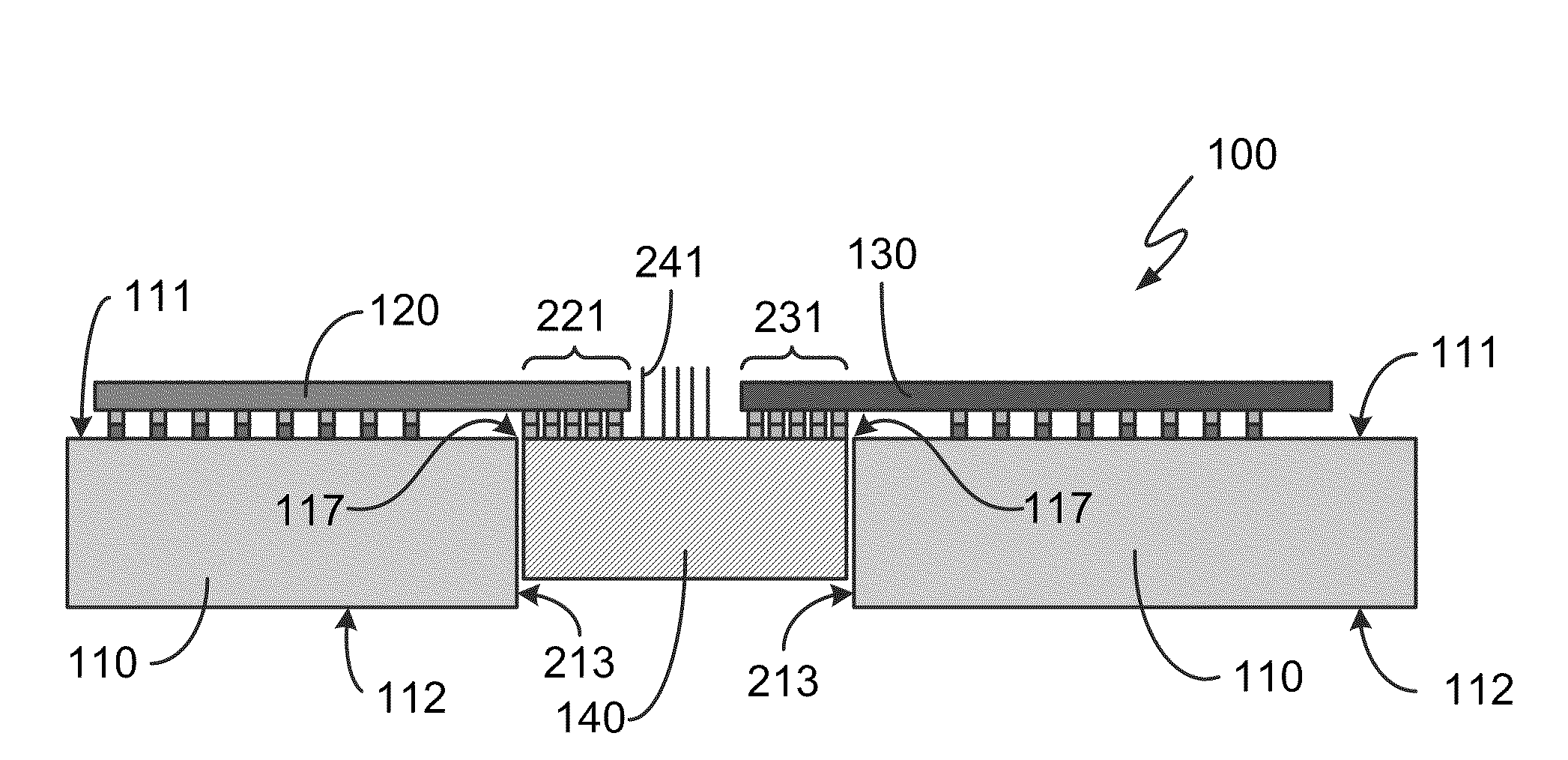
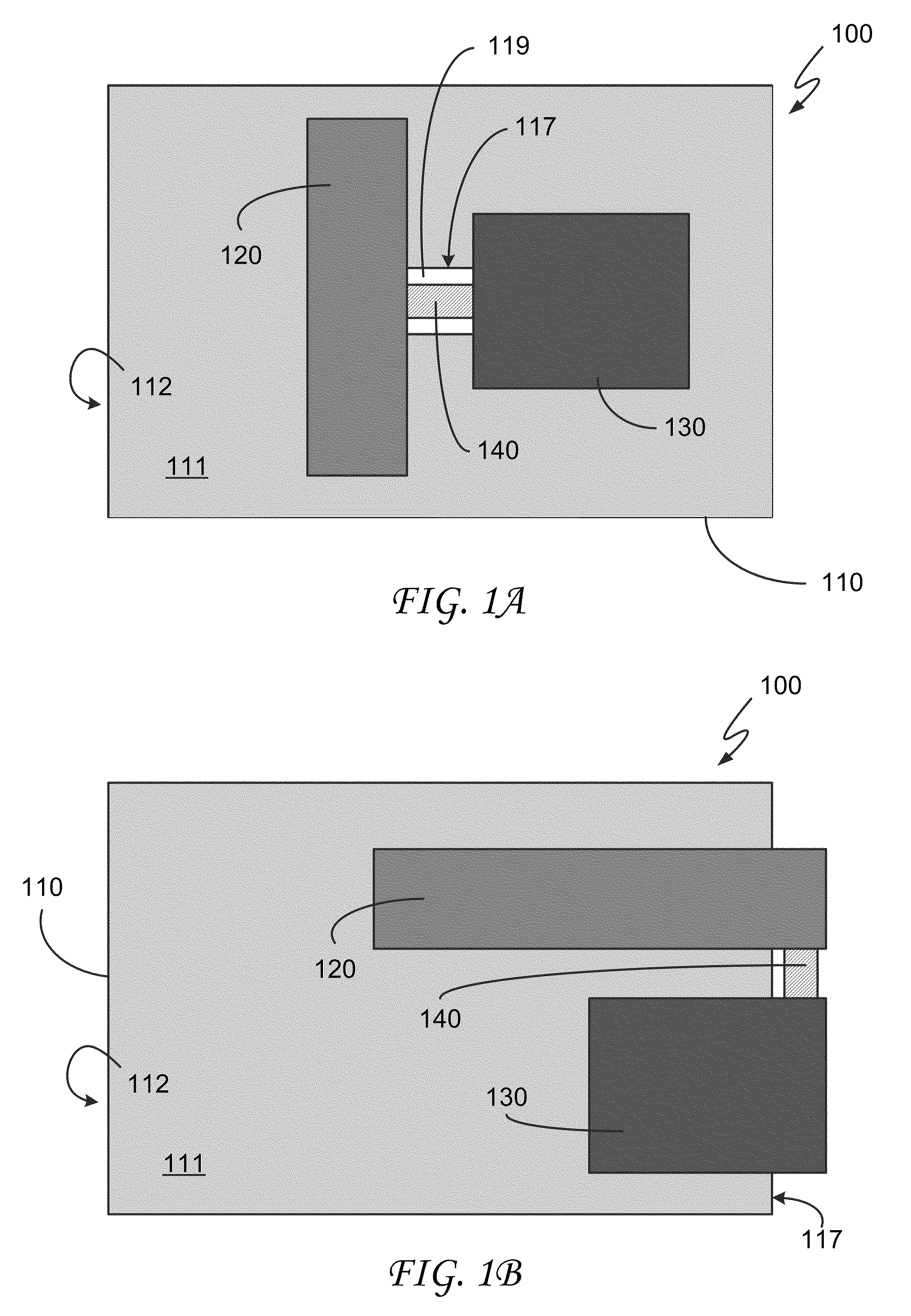
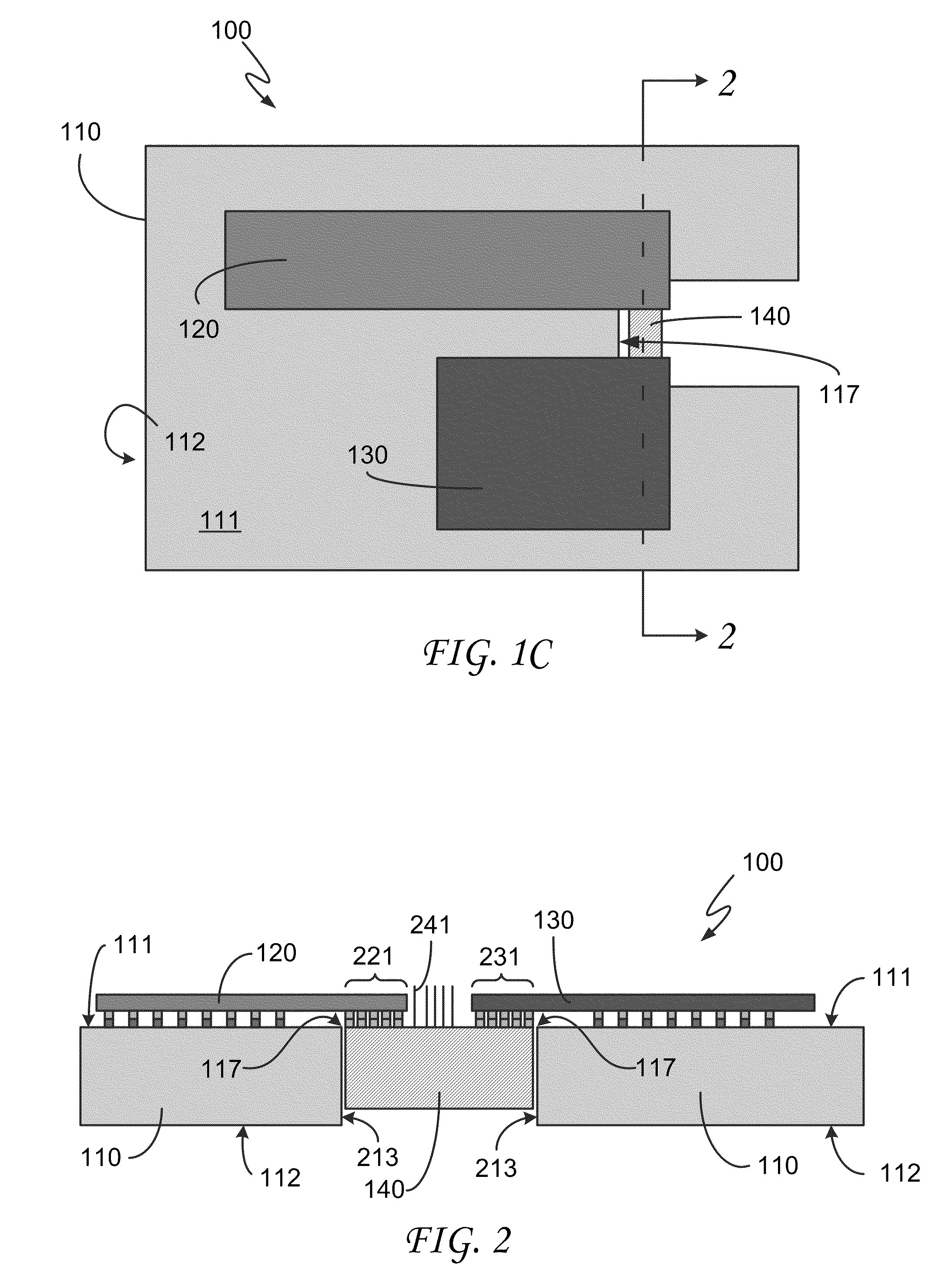
A multi-chip package includes a substrate (110) having a first side (111), an opposing second side (112), and a third side (213) that extends from the first side to the second side, a first die (120) attached to the first side of the substrate and a second die (130) attached to the first side of the substrate, and a bridge (140) adjacent to the third side of the substrate and attached to the first die and to the second die. No portion of the substrate is underneath the bridge. The bridge creates a connection between the first die and the second die. Alternatively, the bridge may be disposed in a cavity (615, 915) in the substrate or between the substrate and a die layer (750). The bridge may constitute an active die and may be attached to the substrate using wirebonds (241, 841, 1141, 1541).

Description

FIELD OF THE INVENTION[0001]The disclosed embodiments of the invention relate generally to multi-chip packages, and relate more particularly to interconnect structures in such packages.BACKGROUND OF THE INVENTION[0002]A continuing focus of the microelectronics industry is the enablement of computer chips (also referred to as dies) having greater density, higher performance, and lower cost. As part of this effort, microelectronic packages containing multiple dies have been developed. Such multi-chip packages (MCPs) offer the potential for increased architectural flexibility at reduced cost but to do so must provide appropriate die-to-die interconnect densities in a way that is cost-effective. The interconnect density is an important consideration because an insufficient number of die connections would limit the bandwidth capability for the affected die interface, and thus logic-logic and / or logic-memory communications would suffer.BRIEF DESCRIPTION OF THE DRAWINGS[0003]The disclosed ...

Claims


Application Information

Patent Timeline
IPC IPC(8): H01L23/538H01L21/60
CPCH01L21/6835H01L23/13H01L24/14H01L24/17H01L24/48H01L24/73H01L24/81H01L25/0652H01L25/0655H01L25/0657H01L2224/13099H01L2224/16145H01L2224/48091H01L2224/48227H01L2224/49175H01L2224/73207H01L2224/73253H01L2224/81001H01L2224/81801H01L2225/0651H01L2225/06513H01L2225/06517H01L2225/06562H01L2924/01029H01L2924/01032H01L2924/01079H01L2924/10253H01L2924/10271H01L2924/10329H01L2924/15153H01L2924/01005H01L2924/01006H01L2924/01033H01L2924/01076H01L2924/014H01L24/49H01L2924/01015H01L2924/1461H01L2924/00014H01L2924/12042H01L24/45H01L2224/1403H01L2224/16225H01L2224/17181H01L2224/32245H01L2224/81005H01L2924/19107H01L2924/00011H01L2924/351H01L2224/141H01L23/5385H01L2924/00H01L2224/45099H01L2224/0401H01L23/12H01L23/48H01L23/5381H01L2224/45147
Inventor BRAUNISCH, HENNINGCHIU, CHIA-PINALEKSOV, ALEKSANDARAU, HINMENGLOTZ, STEFANIE M.SWAN, JOHANNA M.SHARAN, SUJIT
Owner INTEL CORP
Learn More