Photo acoustic sample detector with background compensation

a background compensation and detector technology, applied in the field of photo acoustic detectors, can solve the problems of nosub>2 /sub>detection, inability to modulate wavelength modulation, and signal at the same frequency, and achieve the effect of improving background compensation

Inactive Publication Date: 2011-01-06
KONINKLIJKE PHILIPS ELECTRONICS NV
View PDF7 Cites 5 Cited by
  • Summary
  • Abstract
  • Description
  • Claims
  • Application Information

AI Technical Summary

Benefits of technology

[0003]It is an object of the invention to provide an amplitude m...

Problems solved by technology

A disadvantage of amplitude modulated photo acoustic detection is that the background signal, generated by the modulated laser, is at the same frequency as the sample signal of interest.
Wavele...

Method used


Image

  • Photo acoustic sample detector with background compensation
  • Photo acoustic sample detector with background compensation
  • Photo acoustic sample detector with background compensation

Examples


Embodiment Construction

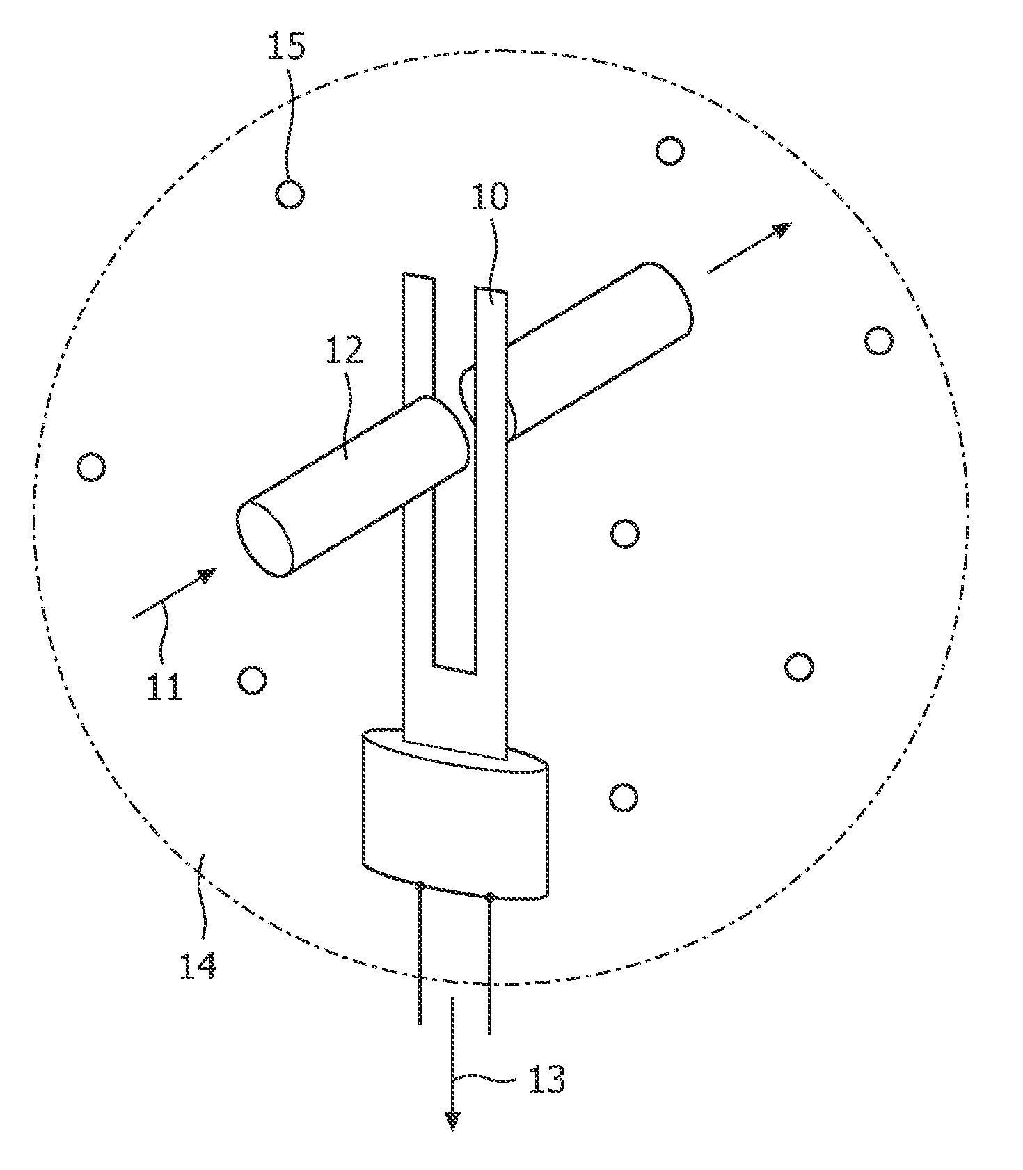
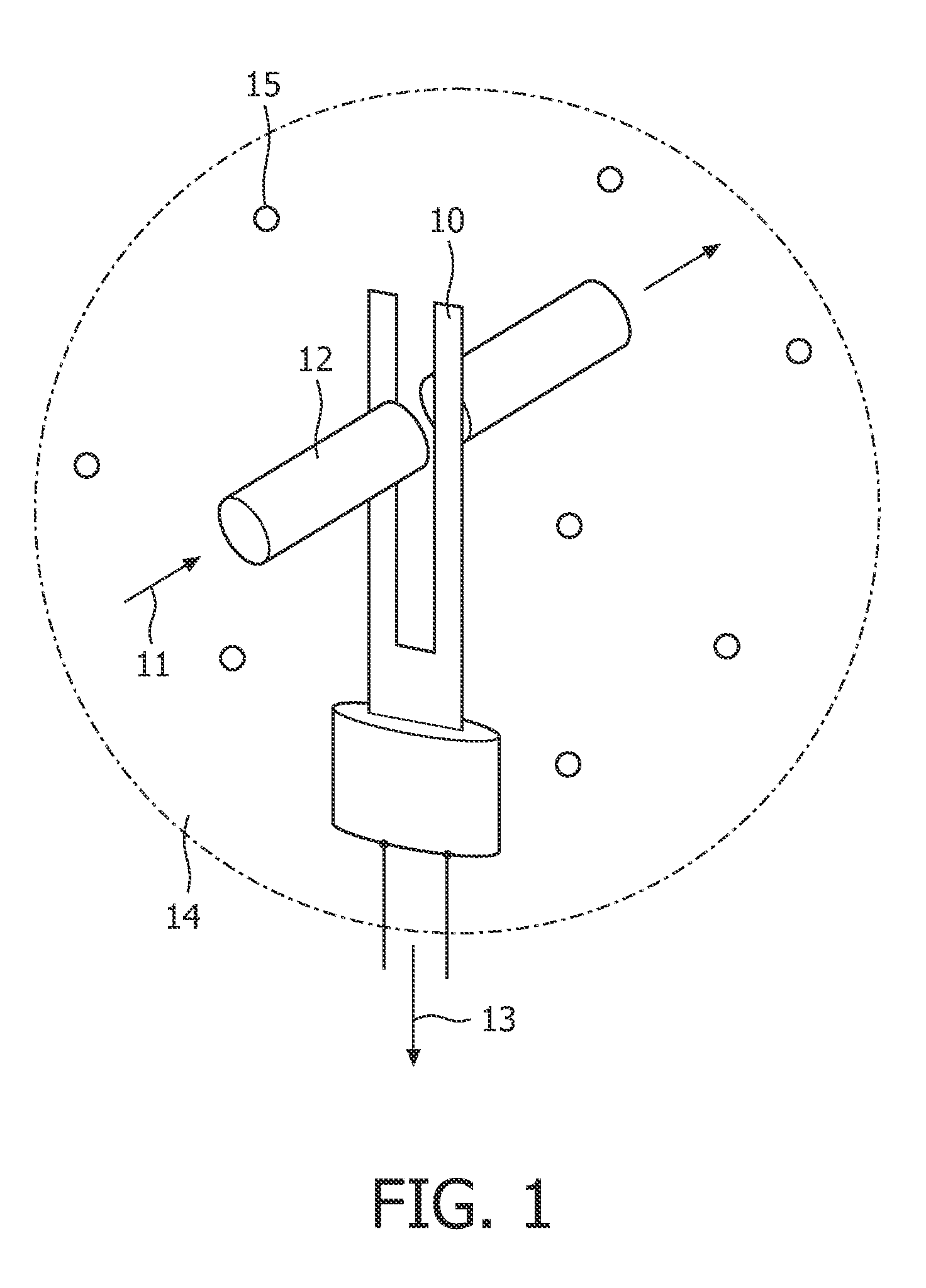
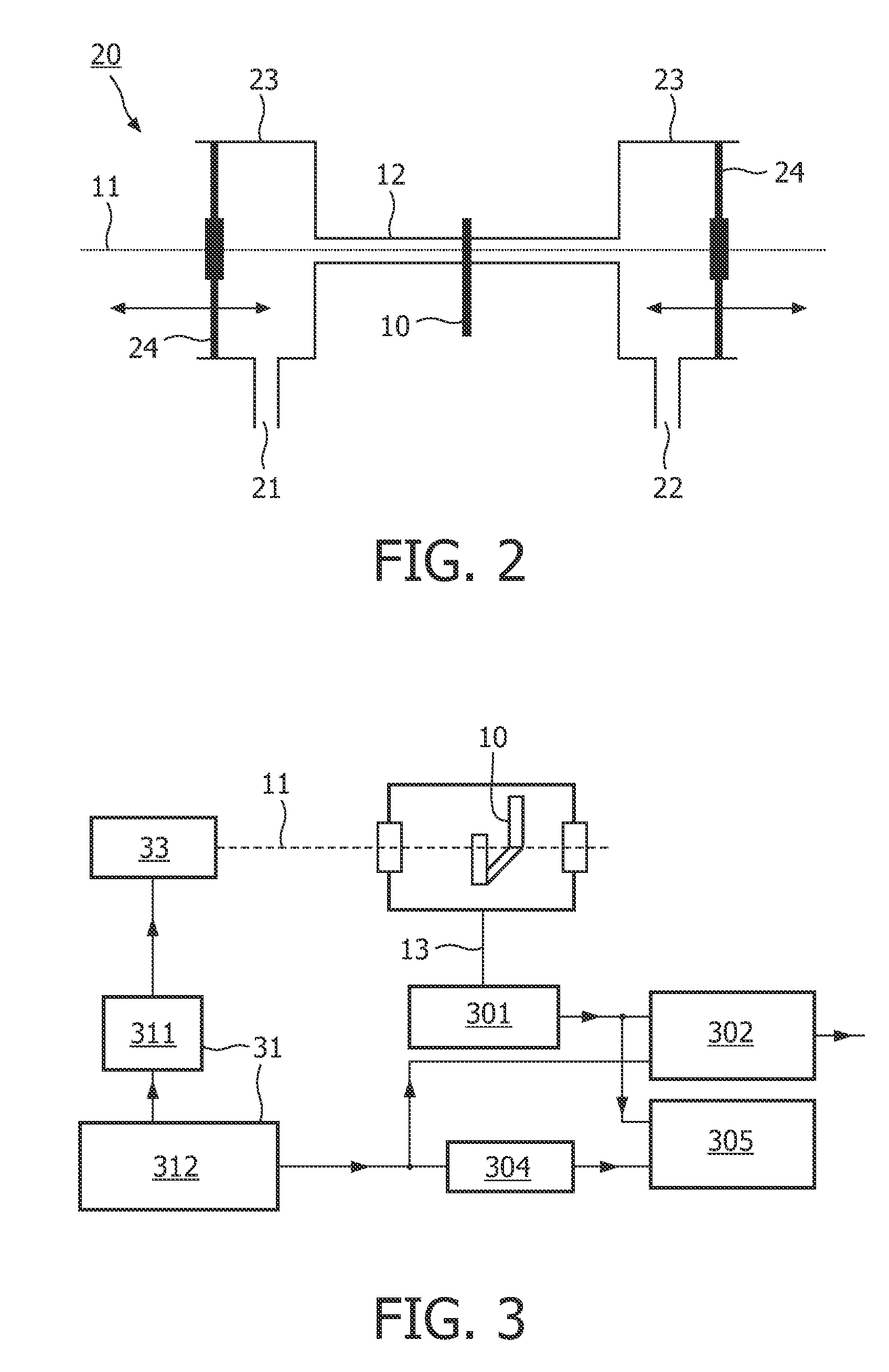
[0020]FIG. 1 shows a perspective view on part of a photo acoustic detector. An amplitude modulated laser beam 11 passes through a gas mixture 14. The gas mixture 14 comprises a low concentration of sample molecules 15. The laser beam 11 excites part of the sample molecules. Sample molecules returning from an excited state to the ground state cause a local temperature increase. The varying intensity of the laser light 11 causes pressure waves in the gas mixture 14. The pressure waves can be detected as sound waves using a resonant pickup element, e.g., in the form of a piezoelectric tuning fork10. The tuning fork 10 may be a quartz tuning fork. An acoustic resonator 12 amplifies the sound waves. The tuning fork 10 converts the sound signal into a detector signal 13 that is led to a processing unit, which will be described in detail with reference to FIGS. 3 and 4.

[0021]It is an advantage of the tuning fork 10, that it is much more sensitive and accurate in detecting the pressure wave...


PUM

PropertyMeasurementUnit
Angleaaaaaaaaaa
Lengthaaaaaaaaaa
Phaseaaaaaaaaaa

Abstract

A photo acoustic detector for detecting a concentration of a sample in a sample mixture, the photo acoustic detector has a light source for producing a light beam for exciting molecules of the sample, a light modulator for modulating an intensity of the light beam for generating pressure variations in the sample mixture, an amplitude of the pressure variations being a measure of the concentration of the sample, and an acoustic cell with an acoustic resonator for amplifying the pressure variations. Furthermore, the photo acoustic detector has a resonant pickup element for converting the pressure variations inside the acoustic resonator into a detector signal, and a processing section for processing the detector signal to generate 1) a sample signal caused by the pressure variations, and 2) a background signal caused by direct excitation of the pickup element by the light beam. The acoustic cell and the pickup element are arranged in such a way that a phase difference between the background signal and the sample signal is close to 90 degrees.

Description

FIELD OF THE INVENTION[0001]This invention relates to a photo acoustic detector for detecting a concentration of a sample in a sample mixture, the photo acoustic detector comprising a light source, a light modulator, an acoustic cell with an acoustic resonator, a resonant pickup element and a processing section. The light source produces a light beam for exciting molecules of the sample. The light modulator modulates an intensity of the light beam for generating pressure variations in the sample mixture, an amplitude of the pressure variations being a measure of the concentration of the sample. The acoustic resonator amplifies the pressure variations. The pickup element converts the pressure variations into a detector signal. The processing section processes the detector signal to generate a sample signal caused by the pressure variations. This invention further relates to a method for manufacturing such a photo acoustic detector.BACKGROUND OF THE INVENTION[0002]Such photo acoustic ...

Claims


Application Information

Patent Timeline
IPC IPC(8): G01J3/44B23P11/00
CPCY10T29/49826G01N21/1702
Inventor KALKMAN, JEROENVAN KESTEREN, HANS WILLEM
Owner KONINKLIJKE PHILIPS ELECTRONICS NV
Why Eureka
Try Eureka