Method and device for palm rejection

a multi-touch device and palm technology, applied in the field of multi-touch devices and methods, can solve the problems of double the amount of conductive films and higher cos

Inactive Publication Date: 2011-01-20
EGALAX EMPIA TECH INC
View PDF7 Cites 75 Cited by
  • Summary
  • Abstract
  • Description
  • Claims
  • Application Information

AI Technical Summary

Benefits of technology

[0006]The objectives and solutions of the technical problems are achieved by the technical means below. A method for palm rejection according to the present invention includes: scanning a touch panel to obtain an image; detecting at least one first touched region based on the image before the touch panel is touched by at least one finger or pen; defining at least one rejection region based on the first touched region when the at least one first touched area is detected; and identifying a touch location corresponding to each of the finger or pen outside the at least one rejection region when the touch panel is being touched by the at least one finger or pen. The objectives and solutions of the technical problems are also achieved by the technical means below. A touch device for palm rejection according to the present invention includes: a touch device for providing an image; and a controller for scanning the touch device for obtaining the image and performing at least the following processes: detecting at least one first touched region based on the image before the touch panel is touched by at least one finger or pen; defining at least one rejection region based on the first touched region when the at least one first touched area is detected; and identifying a touch location corresponding to each of the finger or pen outside the at least one rejection region when the touch panel is being touched by the at least one finger or pen.
[0003]One objective of the present invention is to carry out palm rejection on a multi-touch panel. The panel is first touched by a palm before the detection of a finger or pen to define a rejection region and the touch location of the finger or pen is detected outside that rejection region.
[0012]The present invention can be more fully understood by reading the following detailed description of the preferred embodiments, with reference made to the accompanying drawings, wherein:

Problems solved by technology

However, such a design requires double the amount of conductive films, and thus a higher cost.

Method used


Image

  • Method and device for palm rejection
  • Method and device for palm rejection
  • Method and device for palm rejection

Examples


Embodiment Construction

[0021]The present invention is described by the following specific embodiments. However, the present invention can be broadly applied to embodiments other than those disclosed herein. The scope of present invention is not limited by these embodiments, rather, by the appended claims. For clarity and understanding of the present invention, various elements in the figures are not necessarily drawn to scale; the dimensions of some may be exaggerated relative to others, and some are not described in details.

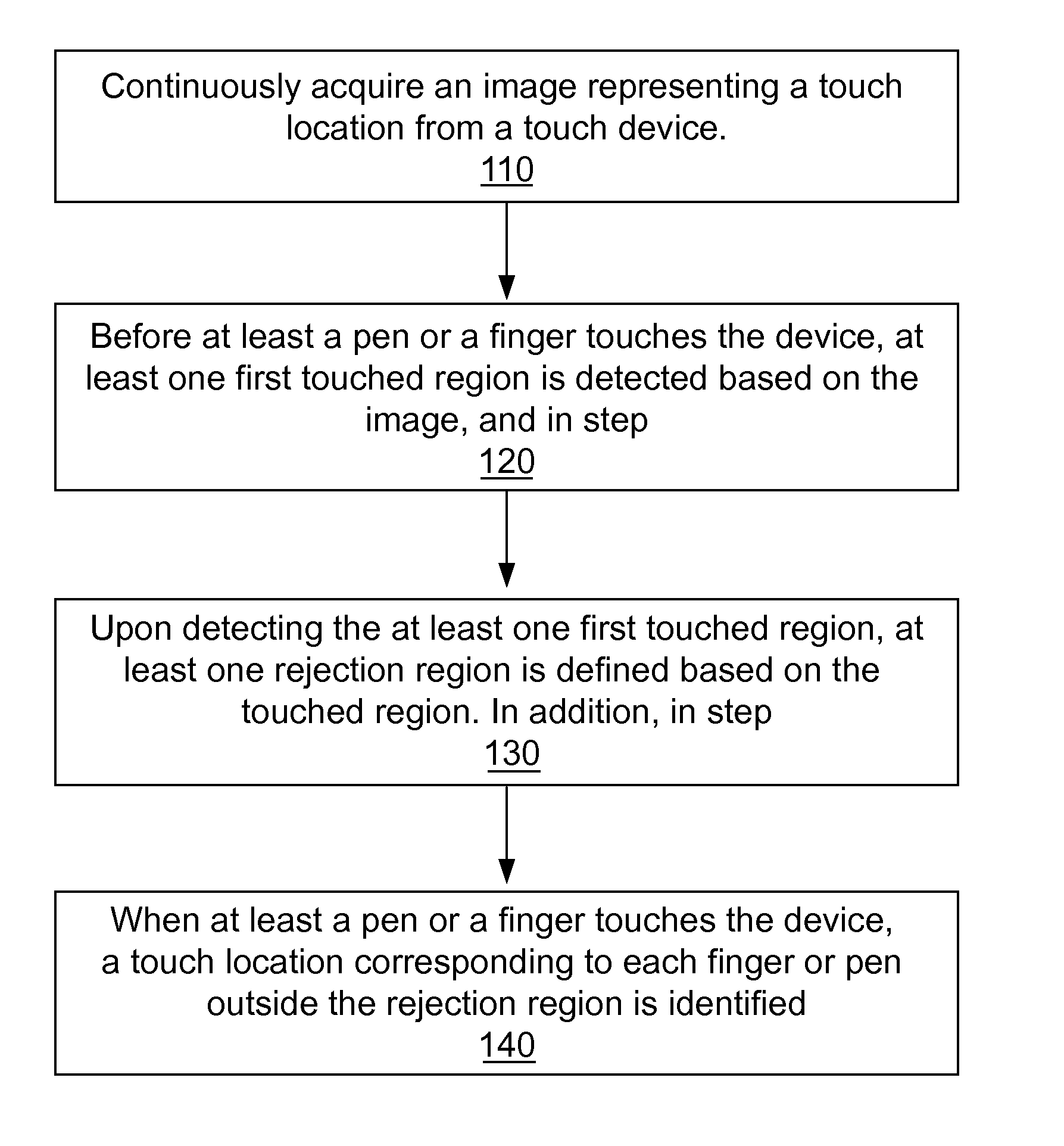
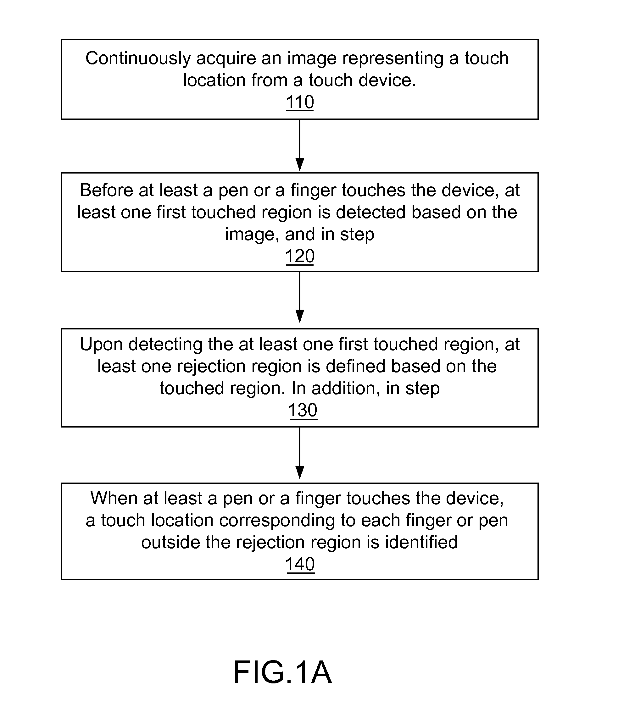
[0022]FIG. 1A is a flowchart illustrating a method for palm rejection according to an embodiment of the present invention. As shown in step 110, a touch device continuously acquires an image representing a touch location. In step 120, before at least a pen or a finger touches the device, at least one first touched region is detected based on the image, and in step 130, upon detecting the at least one first touched region, at least one rejection region is defined based on the touched r...


PUM


Abstract

The present invention carries out palm rejection on a multi-touch panel. The panel is first touched by a palm before the detection of a finger or pen to define a rejection region and the touch location of the finger or pen is detected outside that rejection region. The present invention, when the rejection region and the touch location of the finger or pen have been detected, is able to continuously detecting a region touched by the palm using a detected range defined by the rejection region to determine whether the rejection region needs to be updated.

Description

FIELD OF THE INVENTION[0001]The present invention relates to a multi-touch device and method, and more particularly, to multi-touch device and method for palm rejection.BACKGROUND OF THE INVENTION[0002]U.S. Pat. No. 6,628,269 discloses a method for palm rejection. Compare to a traditional resistive touch device that uses a pair of conductive films facing each other, this patent utilizes two stacked pairs of two-layered conductive films facing each other. The top pair of conductive films is interposed by less densely arranged insulating spacers while the bottom pair of conductive films is interposed by more densely arranged insulating spacers. As a result, only a pointy touch can cause the conductive films of the bottom pair to contact each other, while a touch occupying a larger area (e.g. a palm touch) can only cause the conductive films of the top pair to contact each other, thus achieving palm rejection and obtaining the correct position of the pointy touch. However, such a desig...

Claims


Application Information

Patent Timeline
Patent Type & Authority Applications(United States)
IPC IPC(8): G06F3/041
CPCG06F3/0416G06F3/04186
Inventor YEH, SHANG-TAICHEN, JIA-MING
Owner EGALAX EMPIA TECH INC
Why Eureka
Try Eureka