

Multilayer Piezoelectric Actuator
- Summary
- Abstract
- Description
- Claims
- Application Information
AI Technical Summary
Benefits of technology
Problems solved by technology
Method used
Image

Examples
Embodiment Construction
[0049]Hereafter, the present invention will be made clear by describing specific embodiments of the present invention with reference to the drawings.
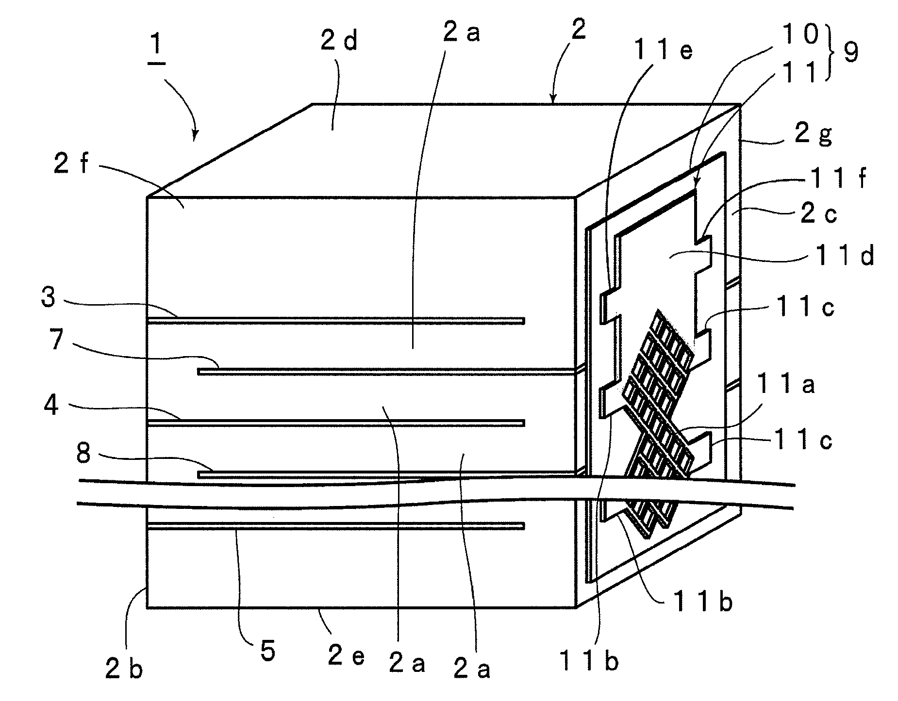
[0050]FIG. 1(a) and FIG. 1(b) are respectively a perspective view and a schematic right side surface view illustrating the exterior of a multilayer piezoelectric actuator according to an embodiment of the present invention.
[0051]A multilayer piezoelectric actuator 1 includes a multilayer piezoelectric body 2. The multilayer piezoelectric body 2 is a monolithic piezoelectric body obtained by firing internal electrodes and piezoelectric ceramic layers by using a co-firing technique.
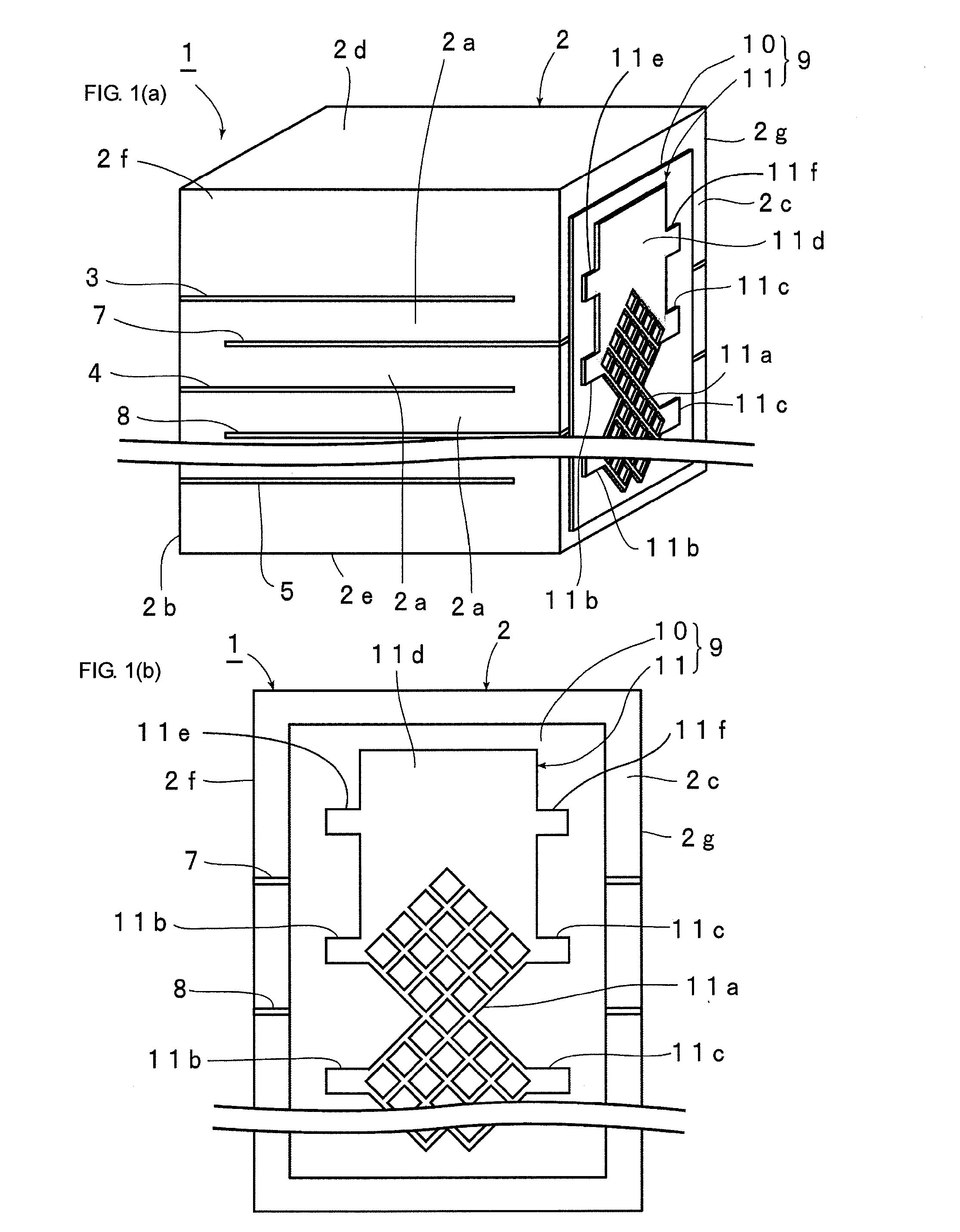
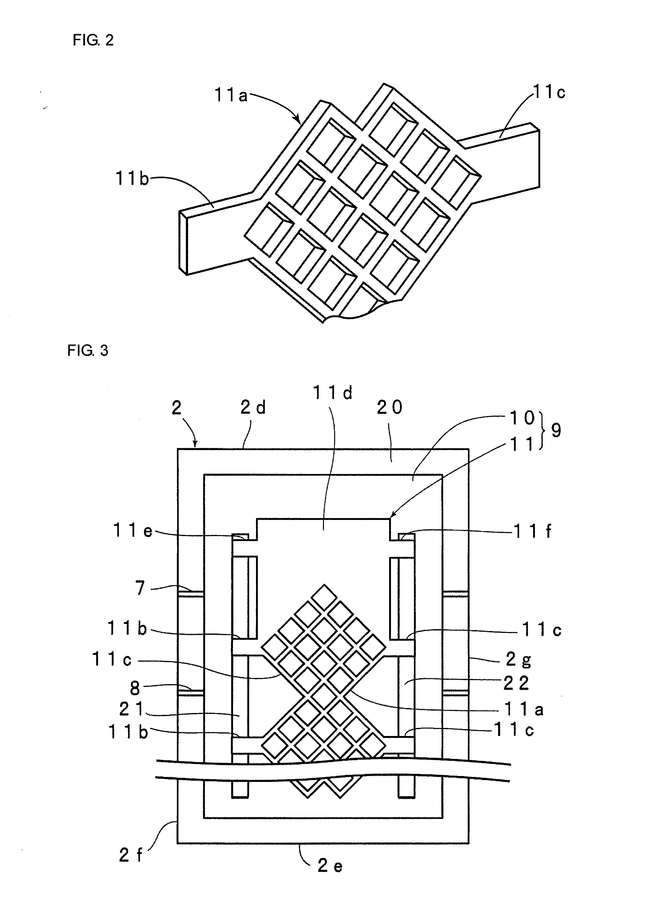
[0052]In more detail, in the multilayer piezoelectric body 2, a plurality of first internal electrodes 3 to 5, which are connected to one potential, and second internal electrodes 7 and 8, which are connected to another potential different from that of the first internal electrodes, are alternately arranged in the stacking direction. The first internal electrod...
PUM
 Abstract
Description
Claims
Application Information