Honeycomb structure

Active Publication Date: 2010-09-23
NGK INSULATORS LTD
View PDF5 Cites 0 Cited by
  • Summary
  • Abstract
  • Description
  • Claims
  • Application Information

AI Technical Summary

Benefits of technology

[0010]According to a honeycomb structure of the present invention, since the outer peripheral wall of each honeycomb segment has protruding portions along the external shape of the first cells and depressed portions along the external shape of the second cells, the contact area between the outer peripheral wall of the honeycomb segment and the bonding member in contact with the honeyco

Problems solved by technology

Since silicon carbide has relatively large thermal expansion coefficient, a honeycomb structure formed by the use of silicon carbide as the framework may cause a defect due to thermal shock upon use if the size is large.
In addition, a defect may be caused due to thermal shock upon combusting and removing trapped particulate matter.
Such a honeycomb

Method used


Image

  • Honeycomb structure
  • Honeycomb structure
  • Honeycomb structure

Examples


Example

Example 1

[0059]As the ceramic raw material, a SiC powder and a metal Si powder were mixed at a mass ratio of 80:20, and to the mixture were added methyl cellulose and hydroxypropoxy methyl cellulose as forming auxiliaries, starch and water-absorbing resin as pore formers, a surfactant, and water, followed by kneading with a vacuum kneader to obtain kneaded clay having a quadrangular prism shape by the use of a vacuum kneader.

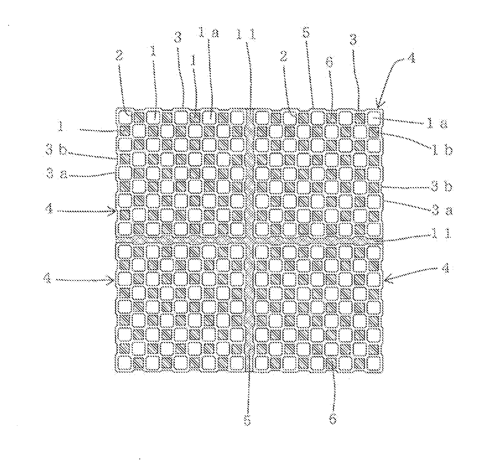
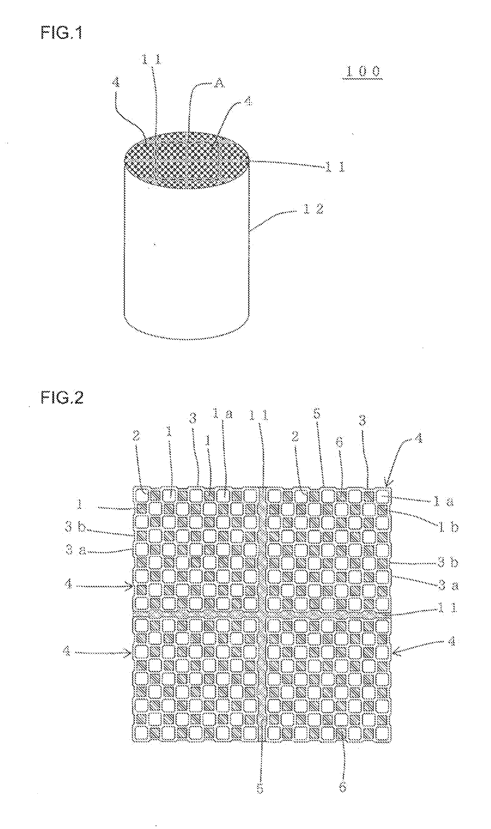
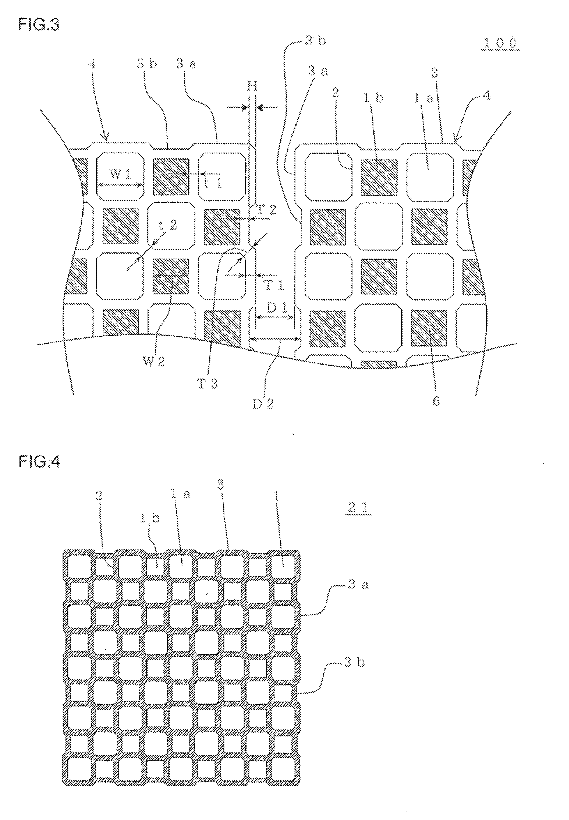
[0060]The kneaded clay having a quadrangular prism shape obtained above was formed, by the use of an extrusion-forming machine, into a honeycomb formed article, as shown in FIG. 4, having a structure having porous partition walls 2 separating and forming a plurality of cells 1 and the outer peripheral walls 3 located in the outermost periphery thereof, the first cells 1a having a large area and the second cells 1b having a small area in a cross section perpendicular to the central axial direction being alternately disposed, the outer peripheral walls 3 each havi...

Example

Examples 2 to 12 and 15 to 20

[0075]Honeycomb structures were manufactured in the same manner as in Example 1 except that the width W1 of the first cells, width W2 of the second cells, partition wall thickness t1, partition wall thickness T1 of the protruding portions, partition wall thickness T2 of the depressed portions, height H of the protruding portions of the outer peripheral wall, distance D1 between protruding portions, and distance D2 between depressed portions were changed as shown in Table 1. The evaluations for “isostatic strength”, “hot vibration test”, “regeneration limit value”, and “pressure loss” were given in the same manner as in Example 1. The results are shown in Table 1. Incidentally, the number of cells was selected in such a manner that each of the honeycomb segments had a bottom face having an external shape size of about 37 mm×37 mm (measured at protruding portions).

Example

Examples 13, 14, 21 and 22

[0076]Honeycomb structures were manufactured in the same manner as in Example 1 except that the honeycomb formed article 21 having the first cell 1a in each of the corner portions as shown in FIG. 4 and the honeycomb formed article 31 having the second cell 1b in each of the corner portions as shown in FIG. 5 were manufactured, that the honeycomb segment 22 formed of the honeycomb formed article 21 and the honeycomb segment 32 formed of the honeycomb formed article 31 were bonded together in such a manner that side faces of the honeycomb segments face each other as shown in FIG. 6, and that the width W1 of the first cell, width W2 of the second cell, partition wall thickness t1, partition wall thickness T1 of the protruding portions, partition wall thickness T2 of the depress ion portions, height H of the protruding portions of the outer peripheral wall, distance D1 between protruding portions, and distance D2 between depressed portions were changed as show...


PUM

PropertyMeasurementUnit
Heightaaaaaaaaaa
Distanceaaaaaaaaaa
Fractionaaaaaaaaaa

Abstract

There is provided a honeycomb structure including a plurality of honeycomb segments having porous partition walls separating and forming a plurality of cells functioning as fluid passages and an outer peripheral wall located in the outermost periphery. The first cells open in an end portion on one side and plugged in the other end portion on the other side and the second cells plugged in the end portion on the one side and open in the other end portion on the other side are alternately disposed. The first cells have an area larger than that of the second cells in a cross section perpendicular to the central axial direction. The outer peripheral wall has protruding portions along an external shape of the first cells and depressed portions along an external shape of the second cells. The honeycomb segments are bonded together with a bonding member.

Description

BACKGROUND OF THE INVENTION AND RELATED ART STATEMENT[0001]The present invention relates to a honeycomb structure, more specifically, to a honeycomb structure capable of inhibiting a honeycomb segment from being detached from a bonding member when combustion of trapped particulate matter (regeneration) is repeated and capable of inhibiting the honeycomb structure to be separated.[0002]A ceramic honeycomb structure excellent in thermal resistance and corrosion resistance is employed as a carrier for a catalytic device or a filter used for an environmental measure, collection of a specific material or the like in various fields such as chemistry, electric power, and iron and steel. In particular, recently, a honeycomb structure plugged alternately in cell open portions on both the end faces as a plugged honeycomb structure is frequently used as a diesel particulate filter (DPF) for trapping particulate matter (PM) discharged from a diesel engine or the like. As a material for the hone...

Claims


Application Information

Patent Timeline
IPC IPC(8): B32B3/12
CPCB01D46/2455Y10T428/24149B01D46/2466B01D46/247B01D46/2474C04B38/0016C04B2111/00793F01N3/0222F01N3/2828F01N2330/06F01N2330/30B01D46/2459Y10T428/24157Y02T10/20C04B35/185C04B35/195C04B35/565Y02T10/12B01D46/2484B01D46/2482B01D46/2478B01D46/2462
Inventor NAGATA, KOJIYAMADA, TOSHIO
Owner NGK INSULATORS LTD
Why Eureka
Try Eureka