Retaining arrangement, sub adaptor and/or drill spindle

Active Publication Date: 2010-05-20
CARDINAL TRADING
View PDF15 Cites 7 Cited by
  • Summary
  • Abstract
  • Description
  • Claims
  • Application Information

AI Technical Summary

Benefits of technology

[0013]According to another aspect the present invention provides a sub adaptor, or consumable, which is adapted to removably mount a retaining device for inhibiting separation of the sub adaptor from a drill spindle

Problems solved by technology

However, these methods often involve damaging the more expensive drill spindle, potential electric shock

Method used


Image

  • Retaining arrangement, sub adaptor and/or drill spindle
  • Retaining arrangement, sub adaptor and/or drill spindle
  • Retaining arrangement, sub adaptor and/or drill spindle

Examples


Example

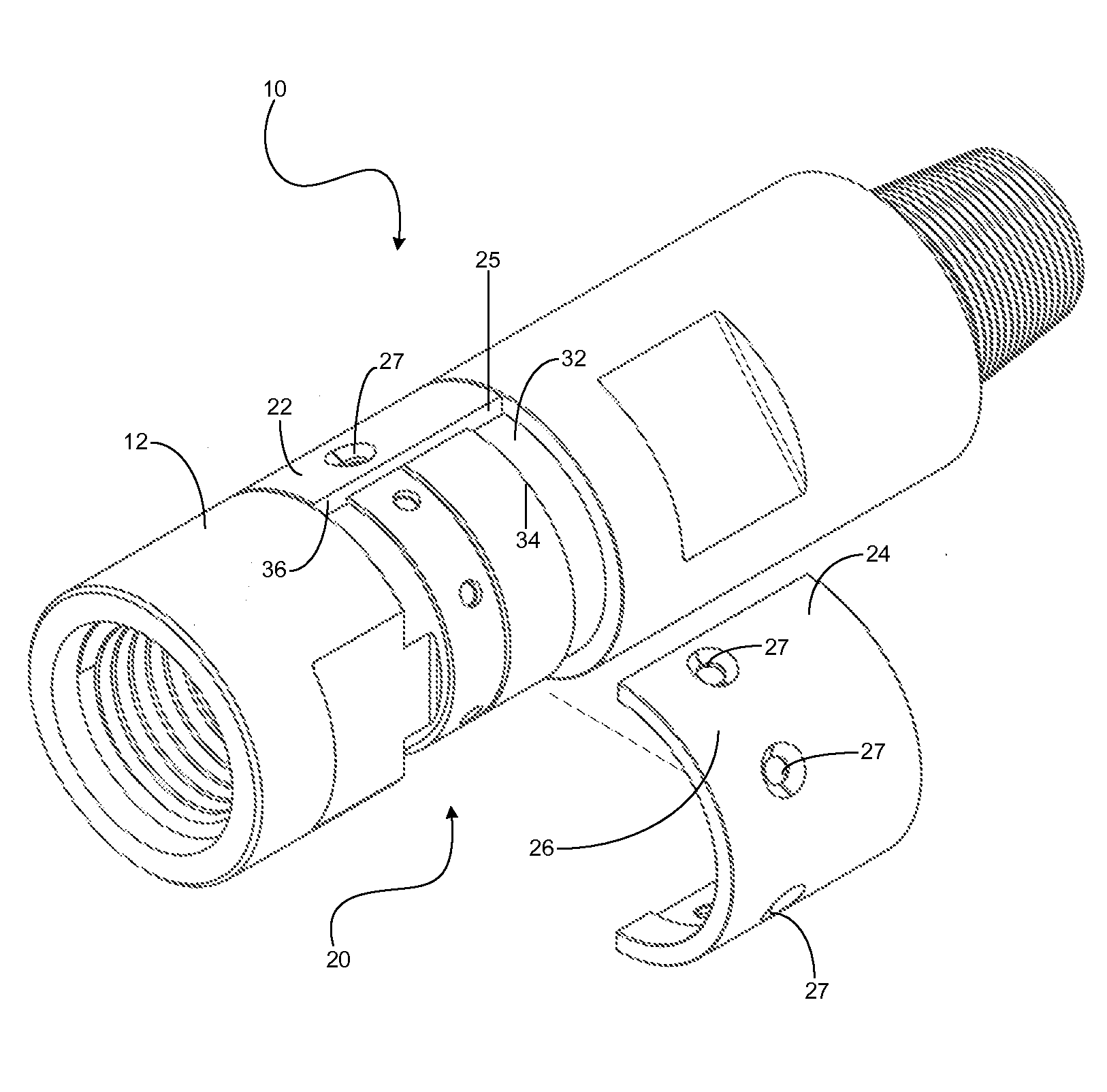
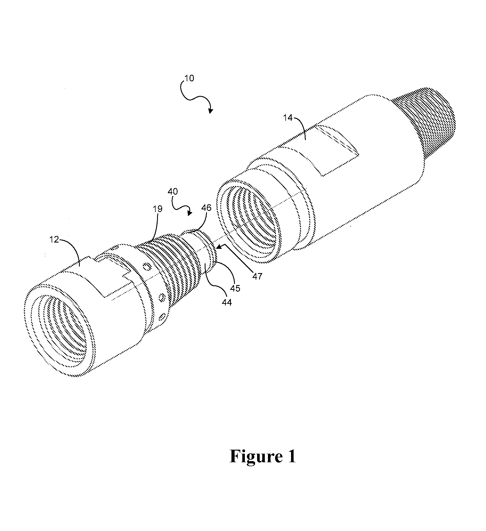
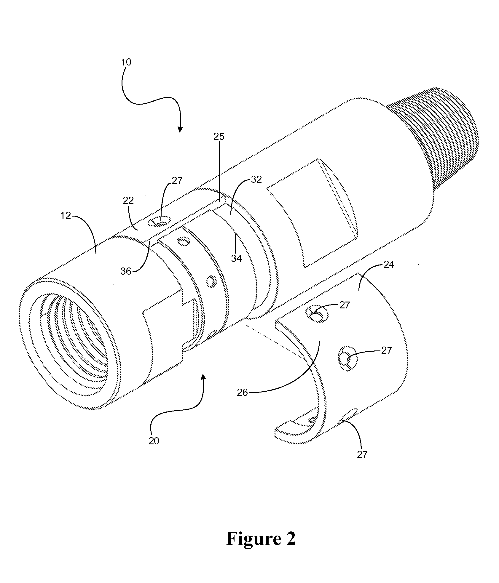
[0019]Referring to the drawings there is shown a coupling arrangement generally indicated at 10, the coupling arrangement 10 being suitable for use with a drilling sub adaptor generally indicated at 12.

[0020]The drilling sub adaptor 12 is adapted to receive a drill consumable. The sub adaptor 12 in use engages with a drill spindle 14 by thread 19.

[0021]In order to inhibit the sub adaptor 12 being disengaged from the spindle 14, a retaining arrangement 20 is provided. The retaining arrangement 20 includes a first retaining body 22 and a second retaining body 24. The retaining bodies 22, 24 are in the form of curved plates, or shells, and are in the embodiment shown, identical half-annular cylinders for improved retention and strength and inter-locking, and one will be described herein, but it is to be understood that the other one incorporates the same features as the first.

[0022]The retaining body 24 includes a connection region 26 adapted to removably connect the retaining body 24 ...


PUM


Abstract

A retaining arrangement suitable for use with a drill string assembly having a sub adaptor and a drill spindle in use connected together, the retaining arrangement including: one or more retaining bodies, the or each retaining body comprising a connection region for removably connecting the or each retaining body to one of the sub adaptor and the drill spindle; and a first retaining or catch region adapted to catch the other of the sub adaptor and drill spindle.

Description

FIELD OF THE INVENTION[0001]The present invention relates generally to connecting and retaining devices, in particular applications, being connectors for use in drilling operations.BACKGROUND OF THE INVENTION[0002]In drilling operations, it is common to use sacrificial or consumable parts in high wear areas. One such area is the drill string assembly. The drill string assembly usually comprises a lesser expensive consumable known as a sub adaptor, which connects the typically more expensive drill spindle to other drill string elements such as a drill bit or drill extension stem. The drill spindle must, in use, operate in forward and reverse, without the sub adaptor uncoupling from the drill spindle.[0003]There have been many ways of locking the sub adaptor to the drill spindle, including: welding tabs between the sub adaptor and spindle. However, these methods often involve damaging the more expensive drill spindle, potential electric shock to welding operators, the need for skilled...

Claims


Application Information

Patent Timeline
IPC IPC(8): F16L55/00
CPCE21B17/03F16L21/08F16L21/06E21B19/16
Inventor LOWRY, JACOB GARTH
Owner CARDINAL TRADING
Why Eureka
Try Eureka