
Eureka
For R&D, Eureka makes reading and utilizing patents & technical documents easy.
Eureka AIR
Designed for self-driven R&D workflows. Generate viable solutions, solve complex R&D challenges, empower your innovation with AI.

Eureka Materials
Designed for material experts only. Revolutionize your material R&D, from search, analyze, to developing new materials.

TechResearch
Generate reliable direction feasibility study reports for your R&D in just a few steps.

TechSeek
Discover and master advanced knowledge NOW. Basics, ideas, possibilities, all at once.

TechMind
As an expert in R&D Theories, TechMind can generates customized viable solutions instantly.

TechRisk
Analyze your overall solution with one click, know your potential R&D risks in advance.

TechMonitor
Get weekly tech updates, stay abreast of the latest tech innovations and key insights.
Fitting with audible misassembly indicator
- Summary
- Abstract
- Description
- Claims
- Application Information
AI Technical Summary
Problems solved by technology
Method used
Image

Examples
first embodiment
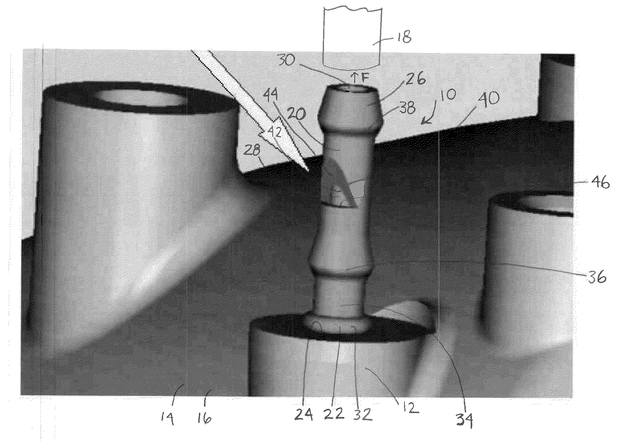
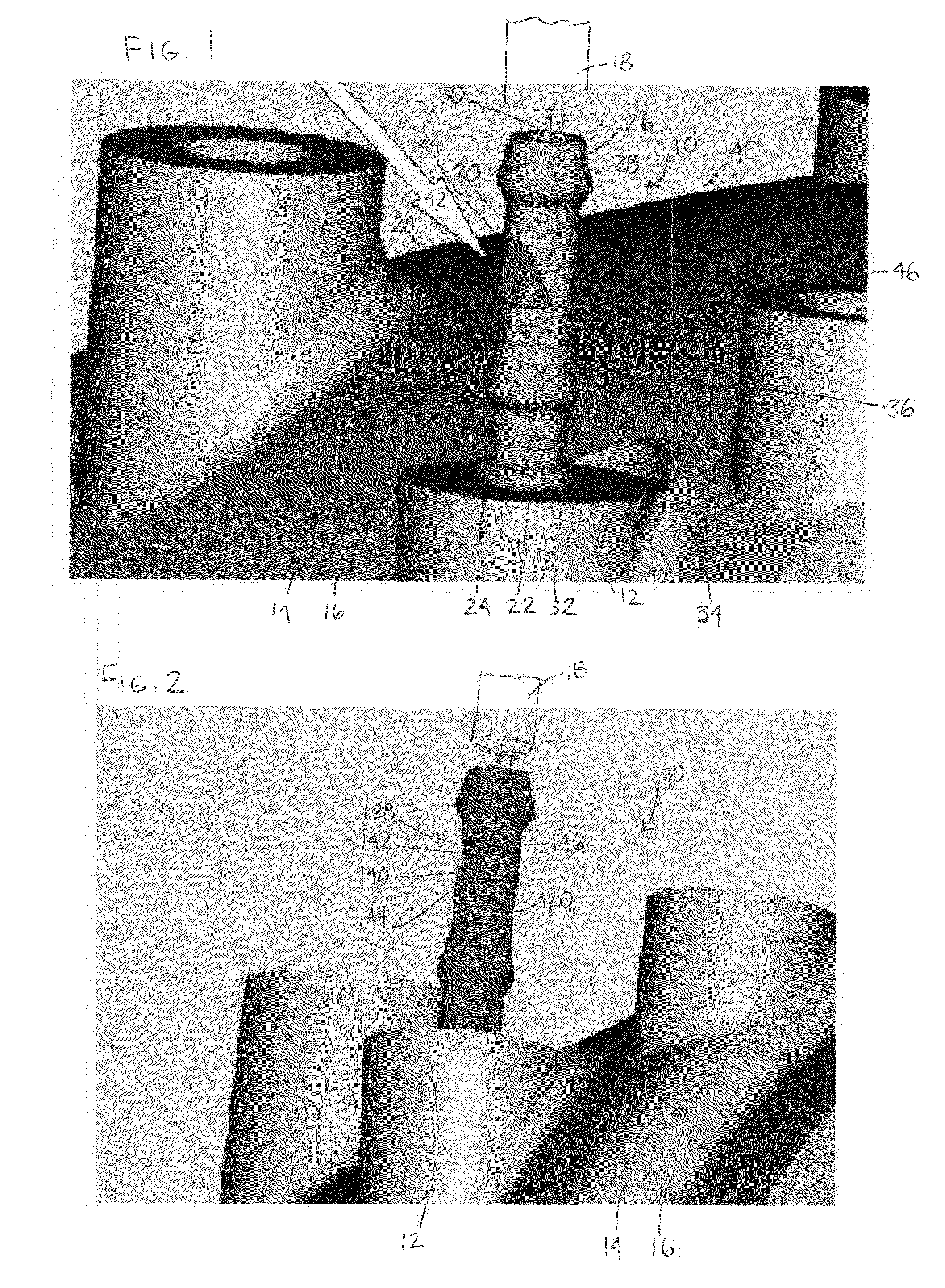
[0007]Referring now to FIG. 1, a fitting is indicated generally at 10 and is disposed in a boss 12 of an engine 14, such as at an intake manifold 16. The boss 12 may provide a passage (not shown) for fluid communication from the intake manifold 16 of the engine 14 to the fitting 10. A hose 18 is received on the exterior surface of the fitting 10. While the fitting 10 is described below with respect to being disposed in the intake manifold 16 of an engine 14, it is possible that the fitting 10 may be used in any hose-to-fitting application of a fluid source and a fluid recipient.
[0008]The fitting 10 has a body 20, which may be generally tubular, having a first end portion 22 configured to be received in a receiving structure 24 of the boss 12, and a second end portion 26 opposite the first end portion. A thru-passage 28 is disposed generally centrally along an axis of the body 20. When the body 20 is received by the receiving structure 24, the thru-passage 28 is in fluid communicatio...
second embodiment
[0019]Referring now to FIG. 2, fitting is indicated generally as 110 and is generally similar to the fitting 10 with exception of the orientation of the misassembly indicator 140. The fitting 110 is received in a receiving structure 24 of the engine where the direction of fluid flow is towards the engine 14 and indicated by the arrow F, for example for vacuum line applications.
[0020]The misassembly indicator 140 includes an opening 142 extending generally radially from the exterior surface to the interior surface of the body 120 providing a second outlet of the thru-passage 128. The misassembly indicator 140 may also include an incident surface 144, and an opposite surface 146 that define the opening 142. The incident surface 144 may be provided at an obtuse angle with respect to the axis of the thru-passage 128 (from the direction of flow), however other orientations are possible. The opposite surface 146 may be provided at any angle relative to the axis of the thru-passage 128.
[00...
PUM
 Abstract
Description
Claims
Application Information
 - R&D Engineer
- R&D Manager
- IP Professional
- Industry Leading Data Capabilities
- Powerful AI technology
- Patent DNA Extraction
Browse by: Latest US Patents, China's latest patents, Technical Efficacy Thesaurus, Application Domain, Technology Topic, Popular Technical Reports.
© 2024 PatSnap. All rights reserved.Legal|Privacy policy|Modern Slavery Act Transparency Statement|Sitemap|About US| Contact US: help@patsnap.com