Spread spectrum clock generator, spread spectrum clock generating method, and circuit, image reading device and image forming apparatus using the spread spectrum clock generator

a technology of spread spectrum clock and generator, which is applied in the direction of image enhancement, instruments, modulation, etc., can solve the problems of emi problem, difficult for the above-mentioned sscgs to control the frequency modulation width with high precision, and electrical interference problem

Inactive Publication Date: 2011-02-03
RICOH KK
View PDF24 Cites 55 Cited by
  • Summary
  • Abstract
  • Description
  • Claims
  • Application Information

AI Technical Summary

Benefits of technology

[0032]comparing the detected modulation width with a predetermined modulation width target value to update the modulation width set value in such a manner that difference between the detected modulation width and the modulation width target value is narrowed;

Problems solved by technology

With increase in scanning density and reading speed of scanners, an electromagnetic interference problem is caused.
Since the VCO gain also varies depending on the semiconductor manufacturing process conditions, operation temperature, supply voltage, etc., it is difficult for the above-mentioned SSCGs to control the frequency modulation width with high precision.
In addition, since the variation in modulation width is the variation in emission noise reduction effect, the EMI problem is caused depending on the property of the VCO itself and / or the use environment.
However, when the average frequency and the modulation width are independently varied, the variation of the modulation width cannot be reduced although only the variation of the average frequency can be reduced.

Method used


Image

  • Spread spectrum clock generator, spread spectrum clock generating method, and circuit, image reading device and image forming apparatus using the spread spectrum clock generator
  • Spread spectrum clock generator, spread spectrum clock generating method, and circuit, image reading device and image forming apparatus using the spread spectrum clock generator
  • Spread spectrum clock generator, spread spectrum clock generating method, and circuit, image reading device and image forming apparatus using the spread spectrum clock generator

Examples


Embodiment Construction

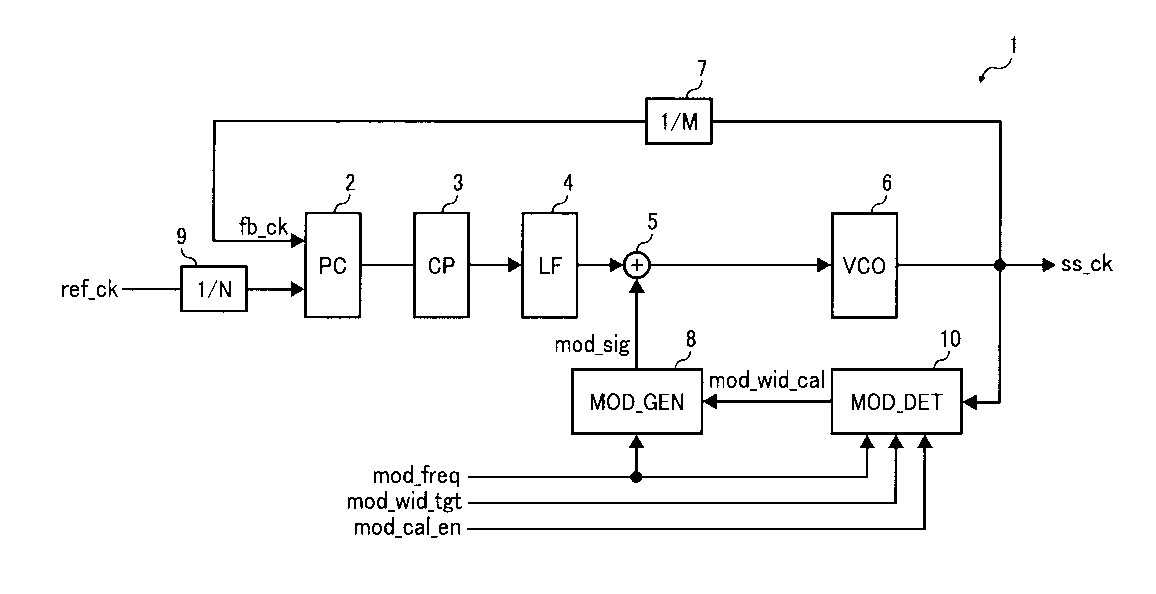
[0054]There is the following correspondence in the following description.

(1) Input clock signal: ref_ck

(2) Feedback clock signal: fb_ck

(3) Phase difference detector: Phase comparator (PC) 2

(4) Voltage supplying device (voltage supplying means): Charge pump (CP) 3

(5) Smoothing device (smoothing means): Loop filter (LF) 4

(6) Voltage controlled oscillator (oscillating means): Voltage controlled oscillator (VCO) 6

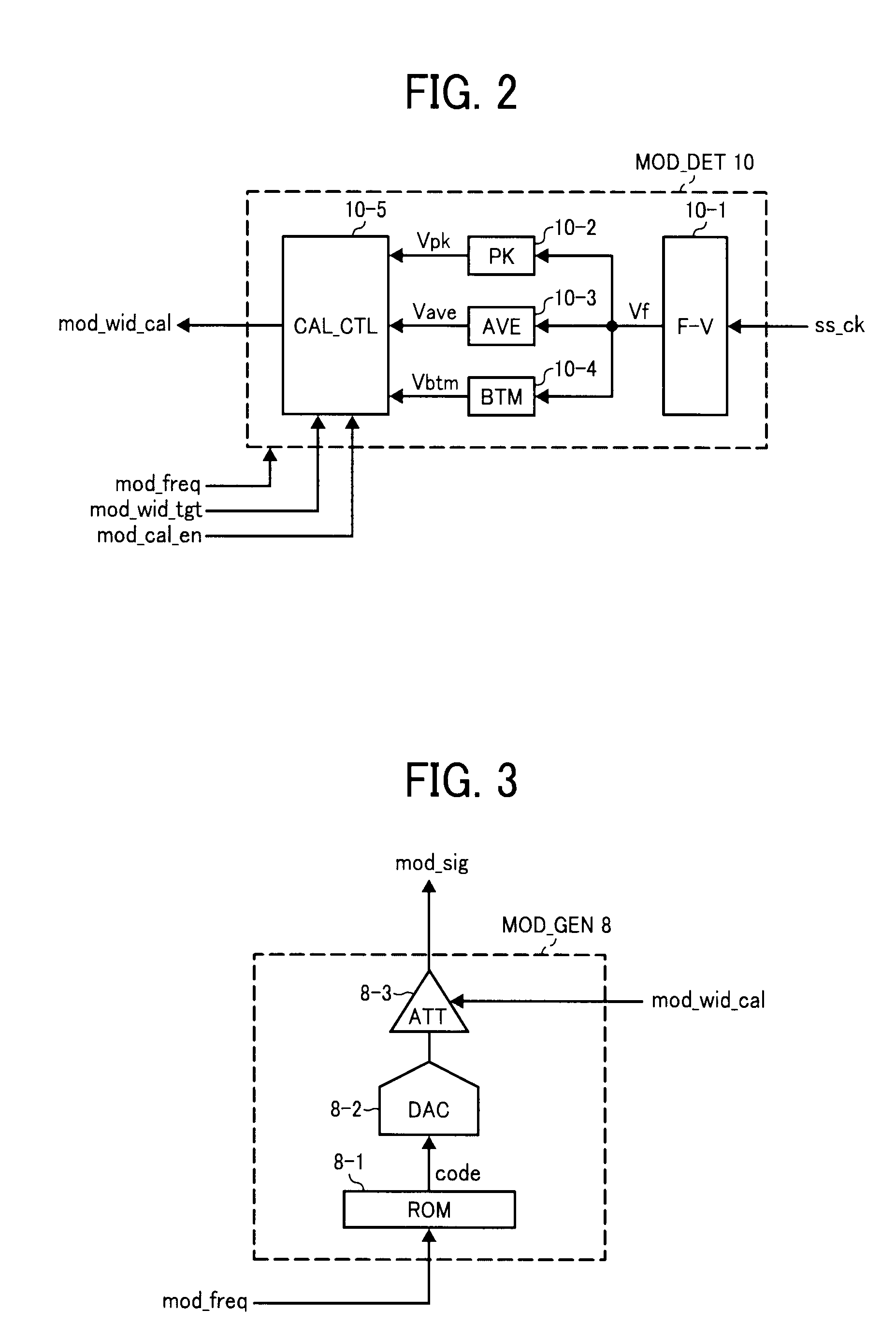
(7) Modulation width set value: mod_wid_cal

(8) Modulation signal: mod_sig

(9) Modulation signal generator: Modulation signal generator MOD_GEN 8

(10) Spread spectrum clock generator: SSCG 1

(11) Spread spectrum clock signal: Modulated clock signal ss_ck

(12) Modulation width: Vmod

(13) Modulation width target value: mod_wid_tgt

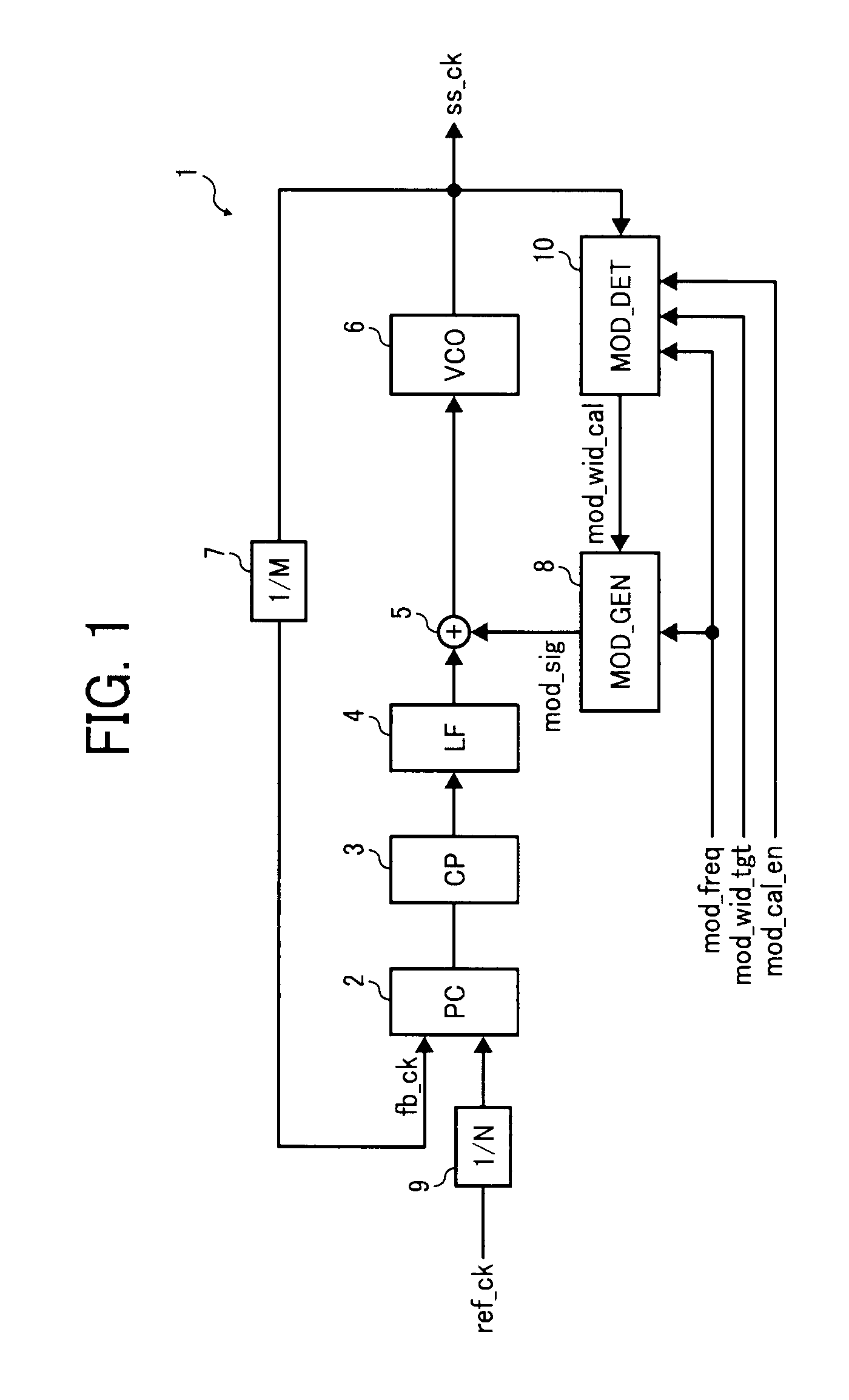
(14) Modulation width detector (modulation width detecting means): Modulation width detector (MOD_DET) 10

(15) Peak frequency: Vpk

(16) Bottom frequency: Vbtm

(17) Average frequency: Vave

(18) Image reading device: Scanner 111

(19) Image forming apparatus: Image fo...


PUM


Abstract

The spread spectrum clock generator (SSCG) includes a phase comparator detecting phase difference between input clock and feedback clock; a charge pump supplying current depending on the phase difference; a loop filter converting the current to smoothed voltage; a voltage controlled oscillator generating a spread spectrum clock signal depending on the smoothed voltage; and a modulation signal generator generating modulation signal having amplitude depending on a modulation width set value. The SSCG further includes a modulation width detector detecting modulation width of the spread spectrum clock signal while comparing the modulation width with a modulation width target value to update the modulation width set value to narrow difference between the detected modulation width and the modulation width target value, followed by feeding back the updated modulation width set value to the modulation signal generator.

Description

BACKGROUND OF THE INVENTION[0001]1. Field of the Invention[0002]The present invention relates to a spread spectrum clock generator. In addition, the present invention relates to a circuit including an integrated circuit including the spread spectrum clock generator. Further, the present invention relates to an image reading device and an image forming apparatus, which use the spread spectrum clock generator. Furthermore, the present invention relates to a spread spectrum clock generating method.[0003]2. Discussion of the Background[0004]Recently, there is a need for an image forming apparatus such as digital copiers, which can produce high quality images at a high speed. Therefore, a need exists for an image reading device (scanner), which can read images at a high dot density and a high speed, so that the scanner can be used for such an image forming apparatus. In attempting to fulfill such a need, the scanning density and reading speed of recent scanners increases more and more. W...

Claims


Application Information

Patent Timeline
Patent Type & Authority Applications(United States)
IPC IPC(8): H04N1/04H03L7/06H04N1/00
CPCH03C3/095H03L7/18H03C3/0916H04N2201/0081H04N1/00994
Inventor NAKAZAWA, MASAMOTO
Owner RICOH KK
Why Eureka
Try Eureka