Systems and methods for determining the mechanical axis of a femur

Active Publication Date: 2011-02-03
SMITH & NEPHEW INC
View PDF53 Cites 237 Cited by
  • Summary
  • Abstract
  • Description
  • Claims
  • Application Information

AI Technical Summary

Benefits of technology

[0021]Additionally, it may be beneficial to provide an improved method of implanting a prosthetic device for

Problems solved by technology

However, not all patients fall within this population subset, nor can all patients achieve the same performance with a universal or standard implant.
In another instance, a patient may have abnormally small or large bone structure.
However, current methods of manufacturing custom implants are generally expensive, require specialized input from a surgeon, and are time-consuming procedures.
Some disadvantages include increased overhead, bulky kits and containers, unnecessary or redundant instruments, large numbers of trials and different sizes, increased OR time, increased sterilization time between surgeries, and increased financial risks to orthopaedic manufacturers which keep larg

Method used


Image

  • Systems and methods for determining the mechanical axis of a femur
  • Systems and methods for determining the mechanical axis of a femur
  • Systems and methods for determining the mechanical axis of a femur

Examples


Example

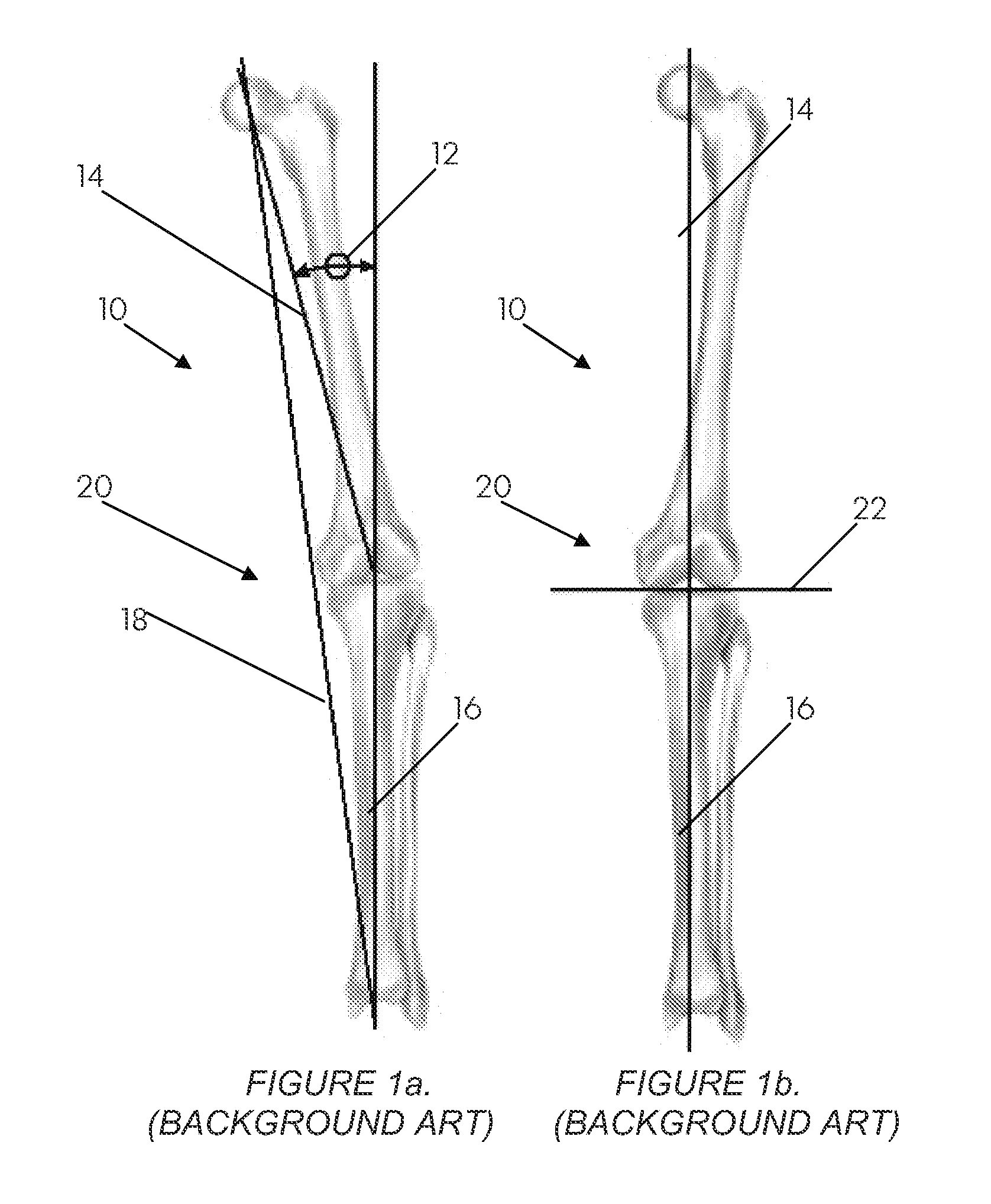
[0060]Stresses within the knee joint are generally uniform and well balanced when the mechanical axis passes through the center of the knee joint. However, in many knee joint diseases, the mechanical axis is disturbed and does not pass through the center of the joint. Such a disturbance overloads portions of the knee joint, eventually leading to damage of even healthy tissue and cartilage. For example, if one condyle experiences degradation, the patella may not track symmetrically within the patellar groove on the femur. This may adversely affect Q-angle and cause anterior knee pain. A patient may compensate for a malaligned mechanical axis by modifying or adjusting their gait pattern to reduce knee pain. However, doing so may lead to other long-term problems such as hip, ankle, or back pain.

[0061]Thus, it is typically the task of a surgeon to restore the mechanical axis of the knee joint during a total or partial replacement surgery, such that that the mechanical axis will be resto...


PUM


Abstract

A method positions a profile of a prosthetic component on the three-dimensional model of a limb. Patient-specific anatomical data of the limb is gathered. First and second anatomical landmarks are identified to determine a first spatial relationship. A third anatomical landmark is identified to determine a second spatial relationship with respect to the first spatial relationship. The profile of the prosthetic component is positioned in all but one degree of freedom. A fourth anatomical landmark is identified to position the profile of the prosthetic component in the one remaining degree of freedom.

Description

CROSS-REFERENCE TO RELATED APPLICATIONS[0001]This application claims the benefit of U.S. Provisional Application No. 60 / 992,977, filed Dec. 6, 2007. The disclosure of each application is incorporated by reference in its entirety.BACKGROUND OF THE INVENTION[0002]1. Field[0003]The present method relates generally to methods of determining the mechanical axis of a patient's limb using anatomical information and more particularly, to methods of providing a customized surgical device configured to guide a cutting tool along a plane perpendicular to the true, three-dimensional mechanical axis of a patient's limb.[0004]2. Related Art[0005]The mechanical axis of the human leg in the frontal plane is defined as a line drawn from the centre of the femoral head to the centre of the ankle joint. In a frontal plane, it normally passes just medial to the centre of the knee joint in the frontal plane. This line assumes sphericity in the femoral head and normal anatomy in the subtalar complex. In a...

Claims


Application Information

Patent Timeline
IPC IPC(8): G06F19/00G06F17/50G16B45/00
CPCA61B17/155A61B17/157A61B17/1703A61B2019/508A61B19/50A61B2019/502A61B17/1764A61B17/1725A61B17/15A61B17/154A61B17/56A61B2017/564A61B2034/102A61B34/10A61B2034/108
Inventor JORDAN, JASON SEANHUGHES, MICHAEL DEANNADZADI, MARK ELLSWORTHMCKINNON, BRIAN W.CRABTREE, PAUL CHARLESMEHL, DAVID
Owner SMITH & NEPHEW INC
Why Eureka
Try Eureka