Load dependent electronic valve actuator regulation and pressure compensation

Active Publication Date: 2017-02-02
DANFOSS POWER SOLUTIONS GMBH & CO
View PDF21 Cites 4 Cited by
  • Summary
  • Abstract
  • Description
  • Claims
  • Application Information

AI Technical Summary

Benefits of technology

[0009]The objective upon which the invention is based is to use pressure information and re-scaled operator input to command actuator velocity in

Problems solved by technology

This can result in poor resolution.
When actuator velocity is 0-100%, poor resolution occurs when the valve opening area is 0-10% and the joystick command is also limited from 0-10%.
A problem with this approach is that when the maximum valve area needs to be oversized for a light load condition, the compensator adds additional pressure drop even when fully open, reducing the maximum lowering velo

Method used


Image

  • Load dependent electronic valve actuator regulation and pressure compensation
  • Load dependent electronic valve actuator regulation and pressure compensation
  • Load dependent electronic valve actuator regulation and pressure compensation

Examples


Embodiment Construction

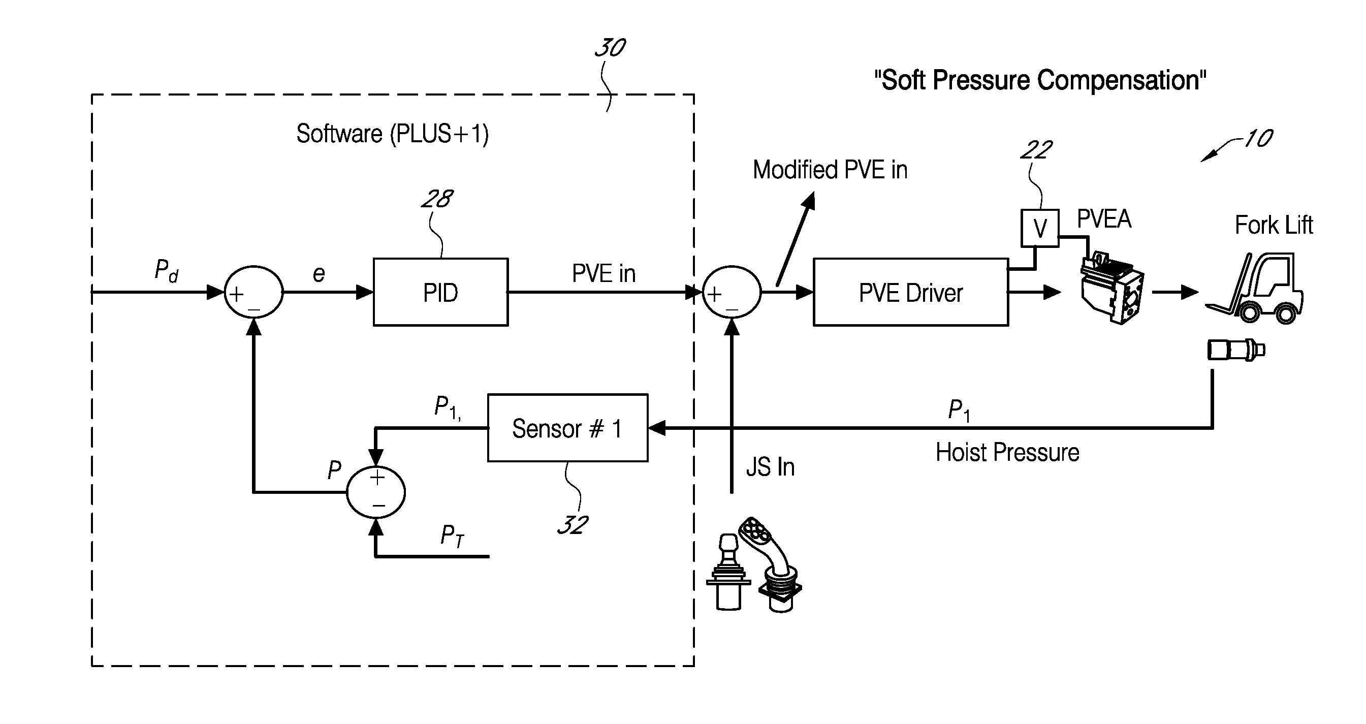
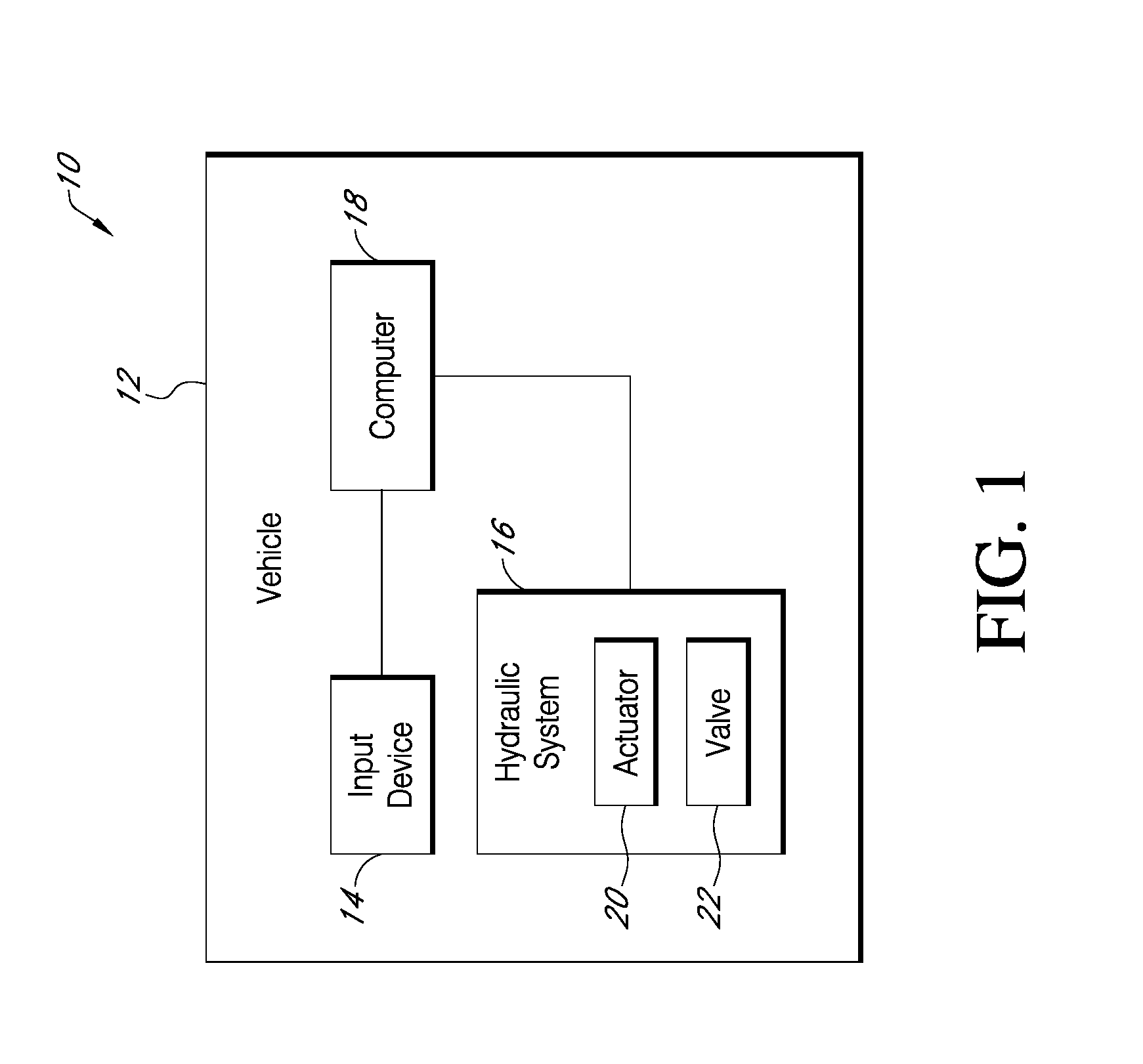
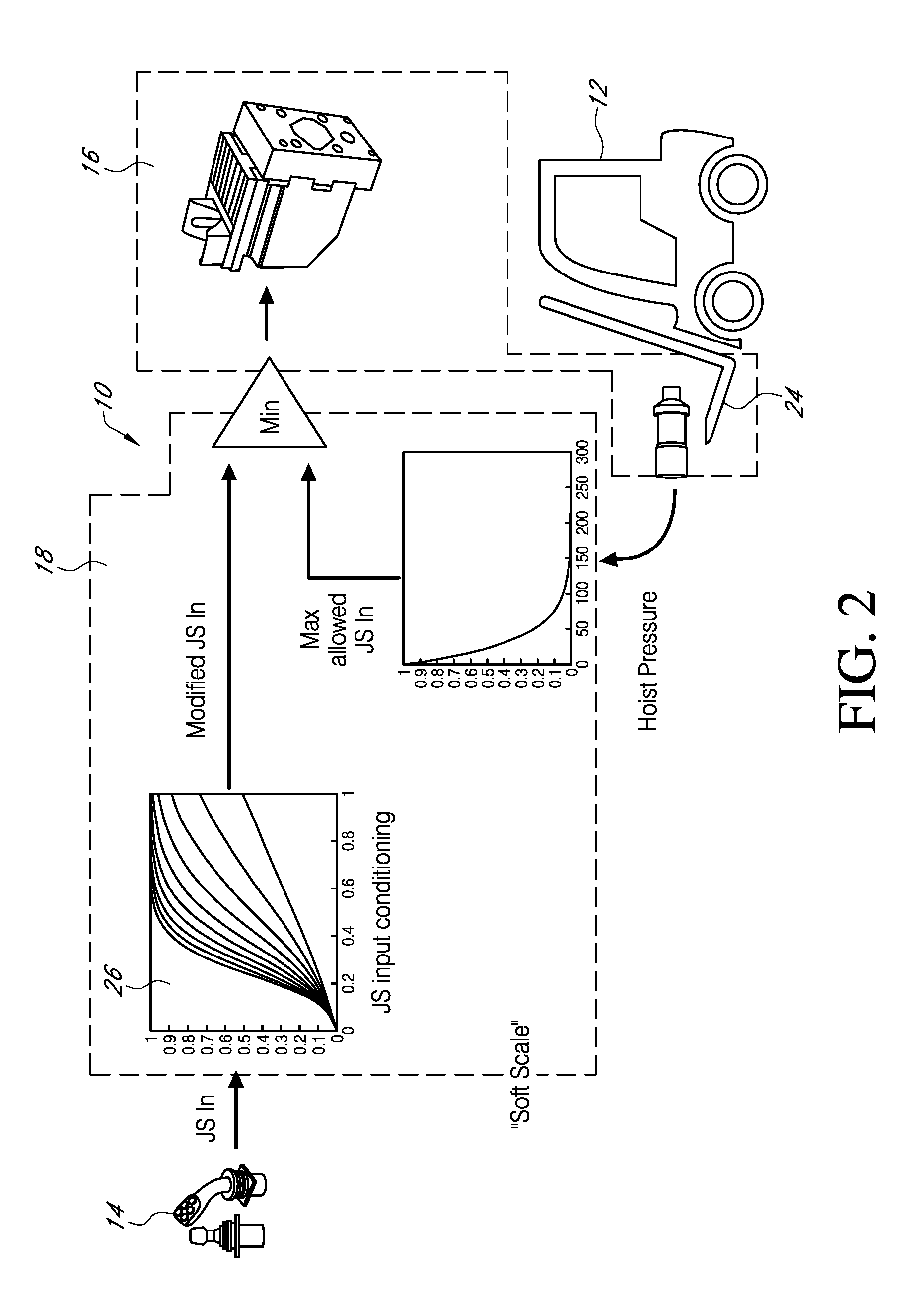
[0017]FIG. 1 shows a schematic view of a system 10 that has load dependent electronic valve actuator regulation and pressure compensation. The system includes a vehicle 12 having an operator input device 14, a hydraulic system 16 for moving a load, and a controller 18 that is connected to input device 14. The hydraulic system has an actuator 20 and a valve 22 that controls flow to and from the actuator 20. For clarity, FIG. 1 shows only the essential elements of system 10 where the system 10 uses pressure information from the hydraulic system 16 to determine a maximum opening area for valve 22 that can be allowed to limit excessive speed of actuator 20. The controller 18 also conditions or re-scales the operator input command to the allowed valve area so that actuator 20 velocity is commanded instead of valve area which results in good input resolution. Poor resolution occurs where actuator velocity is not proportional to the operator input command and the valve opening area. By re-...


PUM


Abstract

A hydraulic control system that uses system pressure information and a rescaled operator input to command valve spool area to control actuator speed. The system uses soft sealing and/or soft pressure compensation.

Description

CROSS REFERENCE TO RELATED APPLICATION[0001]This application claims priority to Provisional Application U.S. Ser. No. 62 / 198,877 filed on Jul. 30, 2015, all of which are herein incorporated by reference in their entirety.BACKGROUND OF THE INVENTION[0002]The invention relates to an electronic valve actuator of a hydraulic system. The invention relates particularly to regulating an electronic valve actuator through load dependence and pressure compensation.[0003]A hydraulic actuator or cylinder is well known in the art and is used to give unidirectional force through a unidirectional stroke. Hydraulic acutators have many applications such as construction equipment, manufacturing machinery and civil engineering.[0004]Hydraulic actuators get their power from pressurized hydraulic fluid. The flow of hydraulic fluid to and from the actuator is controlled by a valve. Depending upon the application, hydraulic actuators are faced with loads that vary greatly. In these situations, the require...

Claims


Application Information

Patent Timeline
IPC IPC(8): B66F9/24B66F9/22F16K31/02
CPCB66F9/24B66F9/22F16K31/02F15B13/02F15B11/04F15B19/007F15B21/087F15B2211/6306F15B2211/6313F15B2211/6346F15B2211/6656F15B2211/75F15B2211/761F15B2211/857E02F9/2203E02F9/2228
Inventor DAS, ABHIJITMAHLUM, LEEWADSLEY, LUKEHITCHCOCK, RICHARDSIPILA, JEFFREY A.JOACHIM, LARRY
Owner DANFOSS POWER SOLUTIONS GMBH & CO
Why Eureka
Try Eureka