Rail lubrication and/or friction modification system within a non-freight carrying intermodal container

a technology of friction modification and intermodal container, which is applied in the direction of rail lubrication, rail wetting/lubrication, railway components, etc., can solve the problems of increasing the risk of locomotive underperformance and train stall, the cost of using onboard lubrication devices on locomotives and traditional freight cars, and the inability to meet the requirements of freight car mounting schemes

Inactive Publication Date: 2011-03-17
UNION PACIFIC RAILROAD
View PDF10 Cites 17 Cited by
  • Summary
  • Abstract
  • Description
  • Claims
  • Application Information

AI Technical Summary

Problems solved by technology

Otherwise, if rail lubricant is dispensed underneath the powered wheels of working locomotives, the risk of locomotive underperformance and train stall increases.
Freight car-mounted schemes are similarly restrictive.
Additionally, using onboard lubrication devices on locomotives and traditional freight cars can be expensive.
This can be quite expensive because of the costs for installing lubrication equipment on each locomotive even though only the one unit in consist (i.e., rear) is used for dispensing the lubricant.
This can be cumbersome.
This may be deemed difficult, as it will most likely require switching locomotive activities and / or switching positions of the freight car within the length of the train at origin and destination terminals.
Moreover, lubrication equipment mounted in / on locomotives and / or freight cars is highly unreliable and requires extensive equipment management controls.
For example, locomotive-mounted schemes tend to subject rail lubrication equipment to high levels of shock-and-vibration when mounted on the truck assemblies at / around the traction motors.
Similar shock and / or vibration may also occur to the lubrication equipment in freight car-mounted schemes.
As such, the costs for installing, running, and repairing (e.g., repairing the lubricant equipment or one or more parts of the containing device itself) the lubrication equipment on locomotives and freight cars are high and can be expensive.

Method used


Image

  • Rail lubrication and/or friction modification system within a non-freight carrying intermodal container
  • Rail lubrication and/or friction modification system within a non-freight carrying intermodal container
  • Rail lubrication and/or friction modification system within a non-freight carrying intermodal container

Examples


Embodiment Construction

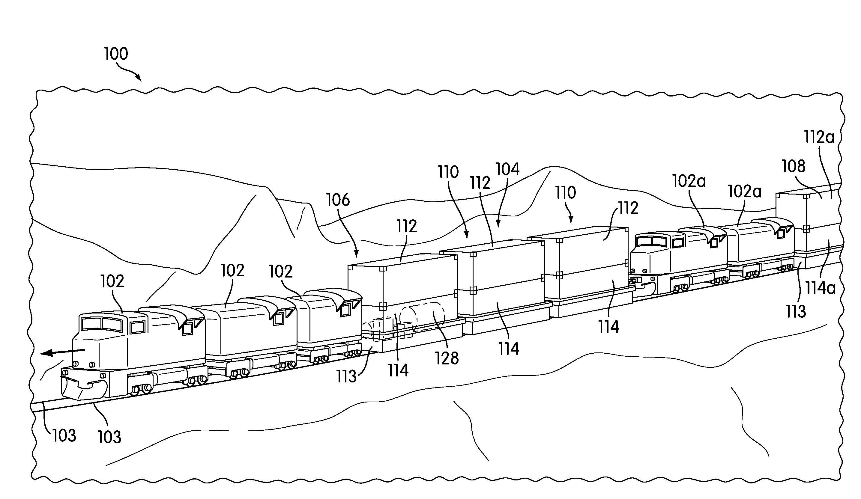
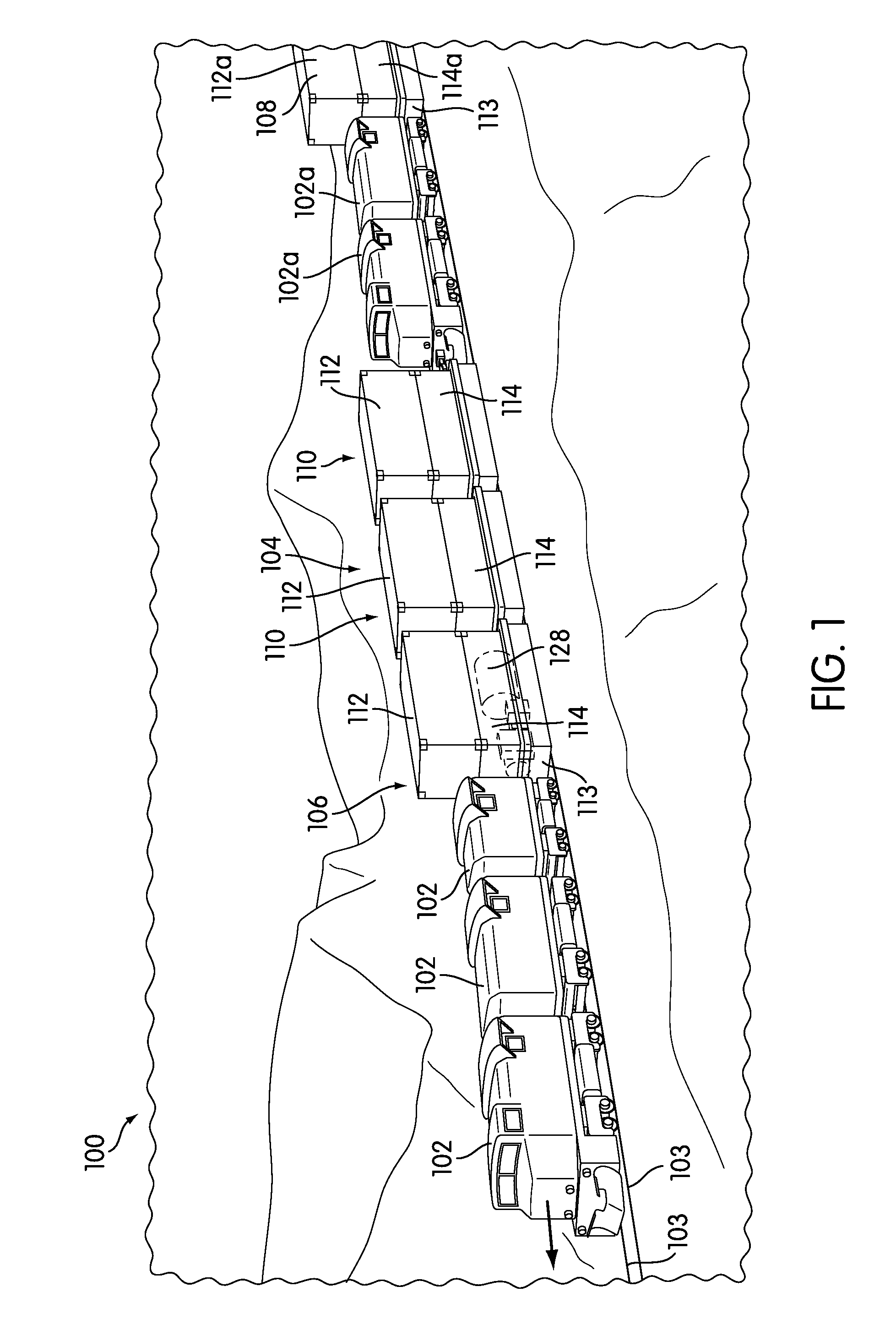
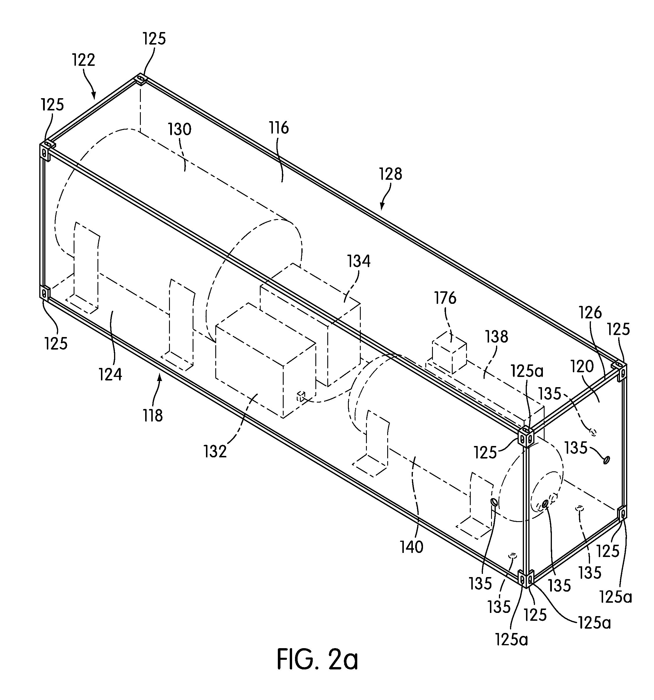
[0025]It is a goal of the present invention to apply lubricant or friction modifiers to a pair of rails of a train track during transportation of train along the track using a modified intermodal container with a lubrication system therein. Though intermodal containers are designed to be used in more than one form of transportation, e.g., railway, waterway, or highway, the embodiments below are herein described pertaining to their use on a railway.

[0026]As noted above, existing applications of onboard rail lubrication equipment focus on installing the equipment onboard either diesel-electric locomotives or rail freight cars. However, the present invention of using onboard lubrication equipment that is installed inside of a modified intermodal (ISO) container would reduce costs of installing and maintenance of the lubrication system, enable or increase the handling of the container using existing equipment, (i.e., container cranes, spreaders, lift systems, chasses and tractors) and r...


PUM


Abstract

A lubrication system is contained within the body of a non-freight carrying intermodal container for lubricating a pair of rails of a train track. The lubrication system includes at least a lubricant holding tank for holding lubricant, a lubricant dispensing pump, and one or more hoses connected to the lubricant holding tank for directing a flow of the lubricant to one or more nozzles. The nozzles are positioned to distribute lubricant to at least a top of the pair of rails. The nozzles may be mounted with respect to a car body, floor, or axle trucks. The container is easily moved and repaired via its corner fittings, for example.

Description

BACKGROUND[0001]1. Field of Invention[0002]The present invention is generally related to a lubrication and / or friction modification system provided within a non-freight carrying intermodal container.[0003]2. Description of Related Art[0004]Typically, rail lubricant is applied on rails of a train track (e.g., such as on top of the rails) such that non-powered wheels of one or more trailing car(s) are in contact with and pulled along the lubricated rails. This is because the rotation of the wheels of the car(s) is caused by the pulling / pushing of one or more powered locomotives. Otherwise, if rail lubricant is dispensed underneath the powered wheels of working locomotives, the risk of locomotive underperformance and train stall increases.[0005]For at least the past 20 years, the railroad industry has focused on installing rail lubrication equipment onboard locomotives and onboard modified freight cars of a train. Generally, locomotive-mounted schemes require careful management when pl...

Claims


Application Information

Patent Timeline
Patent Type & Authority Applications(United States)
IPC IPC(8): B61K3/00
CPCB61K3/02
Inventor IDEN, MICHAEL E.
Owner UNION PACIFIC RAILROAD
Why Eureka
Try Eureka