Reference signal generator and pwm control circuit for LCD backlight

Inactive Publication Date: 2011-03-17
SAMSUNG ELECTRO MECHANICS CO LTD
View PDF7 Cites 6 Cited by
  • Summary
  • Abstract
  • Description
  • Claims
  • Application Information

AI Technical Summary

Benefits of technology

[0009]An aspect of the present invention provides a reference signal generator and a PWM control circuit for an LCD backlight capable of changing the frequency of a reference signal in a soft manner by inserting a frequency buffering interval at such time as a change in a driving mode, such as a change from initial driving to normal driving or a change from the normal driving to protection driving, is made and suppressing the occurrence of peaking by decreasing an abrupt change in the driving frequency.
[0020]According to an embodiment of the present invention, the frequency of a reference signal can be changed in a soft manner by inserting a frequency buffering interval at the time when a change in a driving mode such as a change from initial driving to normal driving or a change from the normal driving to protection driving is made, and occurrence of peaking can be suppressed by decreasing an abrupt change in the driving frequency. Therefore, there is an advantage that internal components can be protected.

Problems solved by technology

However, in such a driving method, controlling a time interval for the lamp's higher frequency output in accordance with the lamp's specifications of the lamp and a driving current in the initial period may be demanding.
In addition, there is a problem that internal components such as a lamp and a transformer may be damaged when an abrupt change from a high frequency to a low frequency or from a low frequency to a high frequency is made.

Method used


Image

  • Reference signal generator and pwm control circuit for LCD backlight
  • Reference signal generator and pwm control circuit for LCD backlight
  • Reference signal generator and pwm control circuit for LCD backlight

Examples


Embodiment Construction

[0027]Exemplary embodiments of the present invention will now be described in detail with reference to the accompanying drawings. The invention may, however, be embodied in many different forms and should not be construed as being limited to the embodiments set forth herein. Rather, these embodiments are provided so that this disclosure will be thorough and complete, and will fully convey the scope of the invention to those skilled in the art. In the drawings, the shapes and dimensions may be exaggerated for clarity, and the same reference numerals will be used throughout to designate the same or like components.

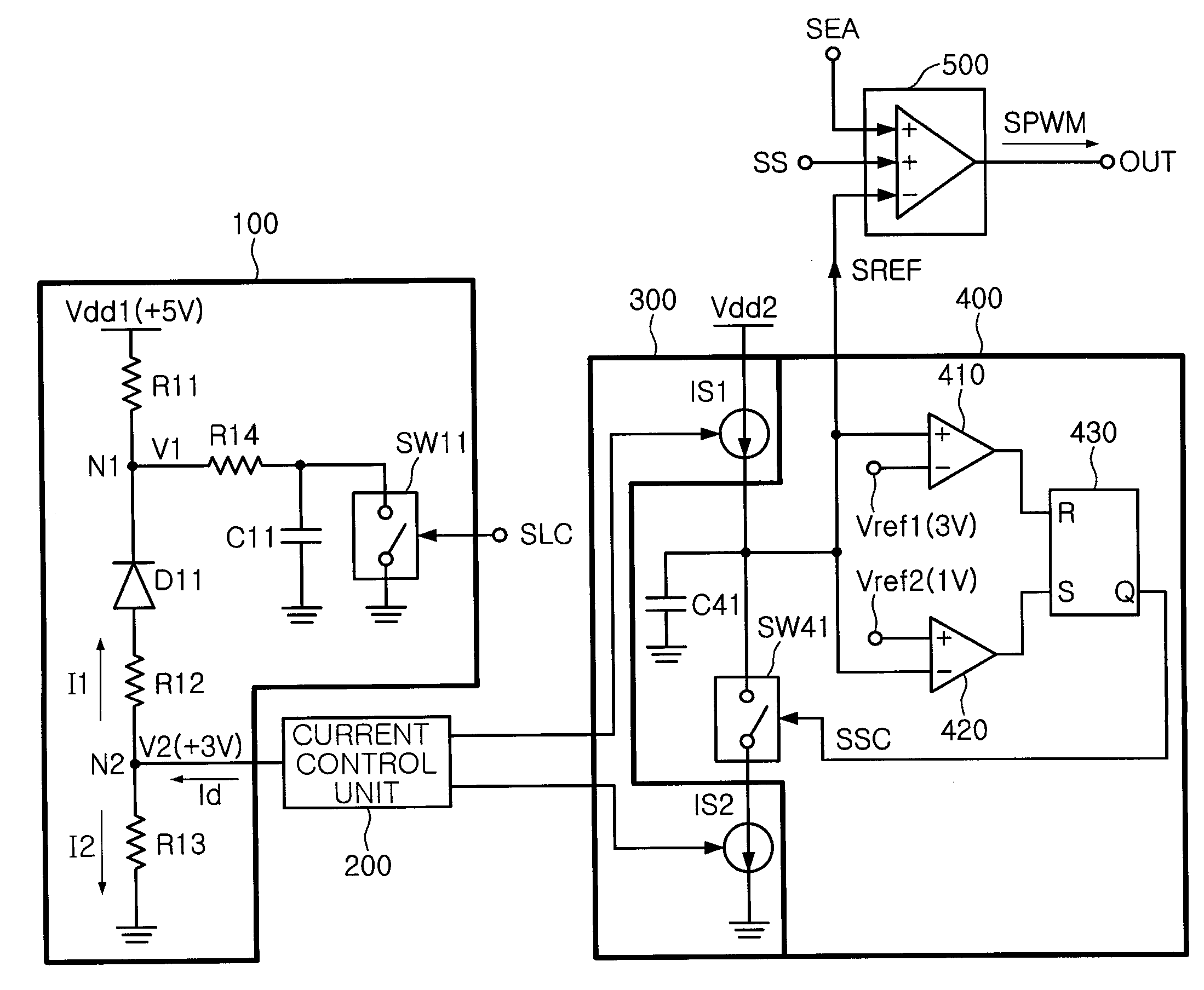
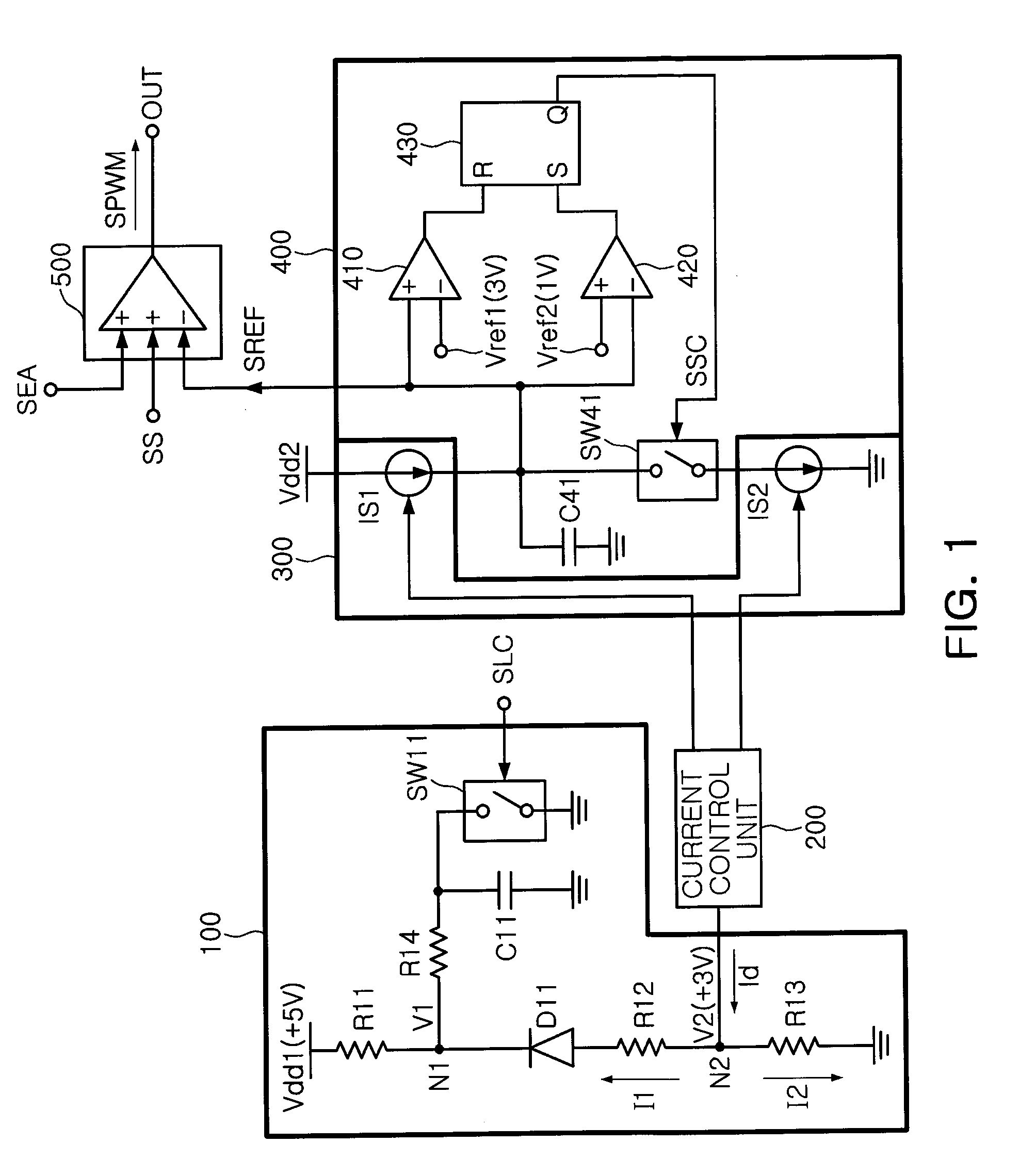
[0028]FIG. 1 is a block diagram of a reference signal generator and a PWM control circuit for LCD backlight according to an embodiment of the present invention. As shown in FIG. 1, the reference signal generator according to an embodiment of the present invention may be configured to include: a variable resistance unit 100 that provides variable resistance changing sequentia...


PUM


Abstract

There are provided a reference signal generator and a PWM control circuit for LCD backlight. The reference signal generator and the PWM control circuit for LCD backlight may be configured to respectively include: a current control unit that controls generation of a variable current sequentially changing; a current generating unit that generates a variable current changing sequentially; and a reference signal generating unit that controls charging until a charged voltage charged by the variable current generated by the current generating unit reaches a first reference voltage level, starts discharging when the charged voltage reaches the first reference voltage level, controls discharging until the charged voltage reaches a second reference voltage level, and generates a triangular wave reference signal that has a frequency buffering interval in which a frequency sequentially changes when the initial driving completion signal or the protection signal is input.

Description

CROSS-REFERENCE TO RELATED APPLICATIONS[0001]This application claims the priority of Korean Patent Application No. 10-2009-0086651 filed on Sep. 14, 2009, in the Korean Intellectual Property Office, the disclosure of which is incorporated herein by reference.BACKGROUND OF THE INVENTION[0002]1. Field of the Invention[0003]The present invention relates to a reference signal generator that can be used in an LCD backlight inverter and a PWM control circuit for LCD backlight, and more particularly, to a reference signal generator and a PWM control circuit capable of changing the frequency of a reference signal in a soft manner by inserting a frequency buffering interval when there is a change in the driving mode such as a change from initial driving to normal driving or a change from normal driving to protection driving.[0004]2. Description of the Related Art[0005]Generally, backlight inverters used in LCD (Liquid Crystal Display) TV sets or LCD monitors to which CCFLs (Cold Cathode Fluo...

Claims


Application Information

Patent Timeline
IPC IPC(8): H05B37/02G05F3/02
CPCH05B41/285H05B41/24H05B41/38
Inventor JANG, YU JINCHEON, JEONG IN
Owner SAMSUNG ELECTRO MECHANICS CO LTD
Why Eureka
Try Eureka