Loudspeaker diaphragm and loudspeaker including the loudspeaker diaphragm

Inactive Publication Date: 2011-12-29
ONKYO KK
View PDF9 Cites 17 Cited by
  • Summary
  • Abstract
  • Description
  • Claims
  • Application Information

AI Technical Summary

Benefits of technology

[0016]According to the present invention, the diaphragm portion of the loudspeaker diaphragm includes, at the outer peripheral end thereof, the outer wall portion provided upright in the direction substantially parallel to the vibrating direction of the diaphragm portion, and the outer peripheral surface of the outer w

Problems solved by technology

The vibration system member thus obtained has a problem in that poor bonding may be caused depending on the combination of the respective members, and a problem in that characteristics may fluctuate due to a variation in adhesive application amount.
Further, in order to prevent an operation failure of the loudspeaker, it is necessary to use a highly-accurate assembly jig, which leads to a problem of poor productivity.
In additio

Method used


Image

  • Loudspeaker diaphragm and loudspeaker including the loudspeaker diaphragm
  • Loudspeaker diaphragm and loudspeaker including the loudspeaker diaphragm
  • Loudspeaker diaphragm and loudspeaker including the loudspeaker diaphragm

Examples


Example

Example 1

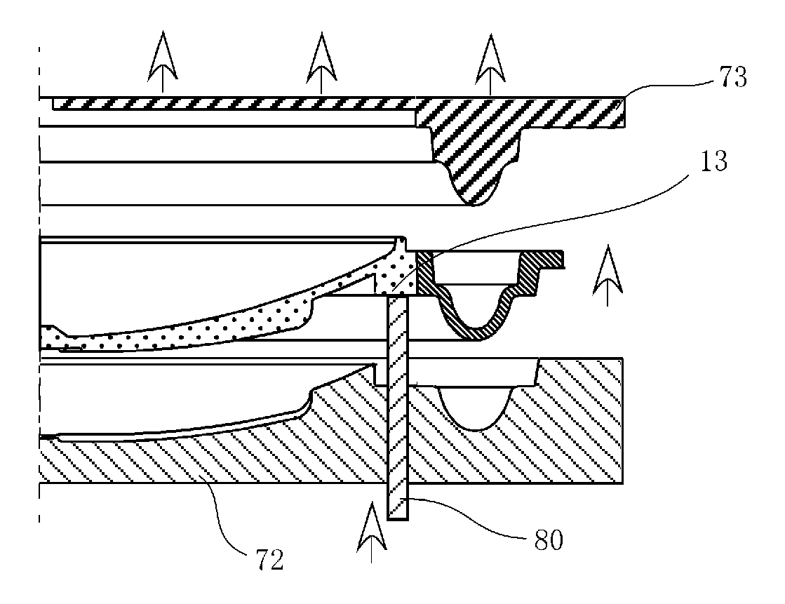
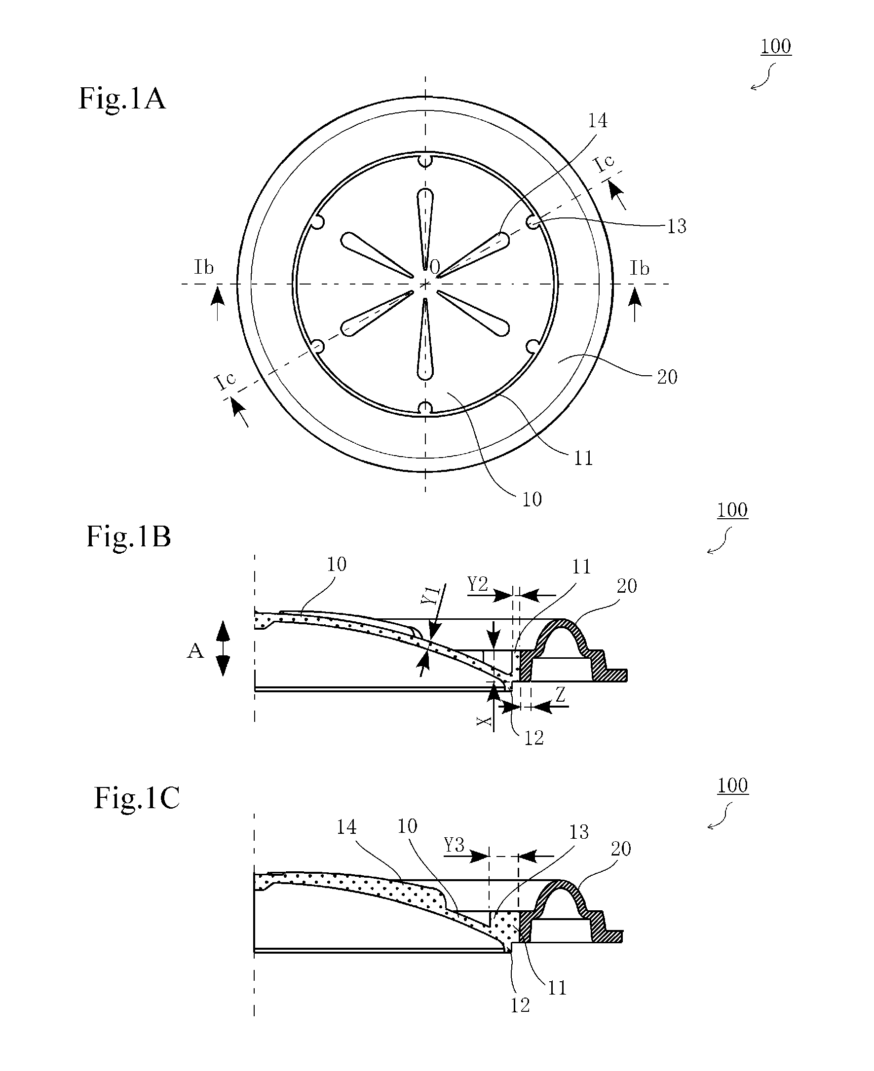
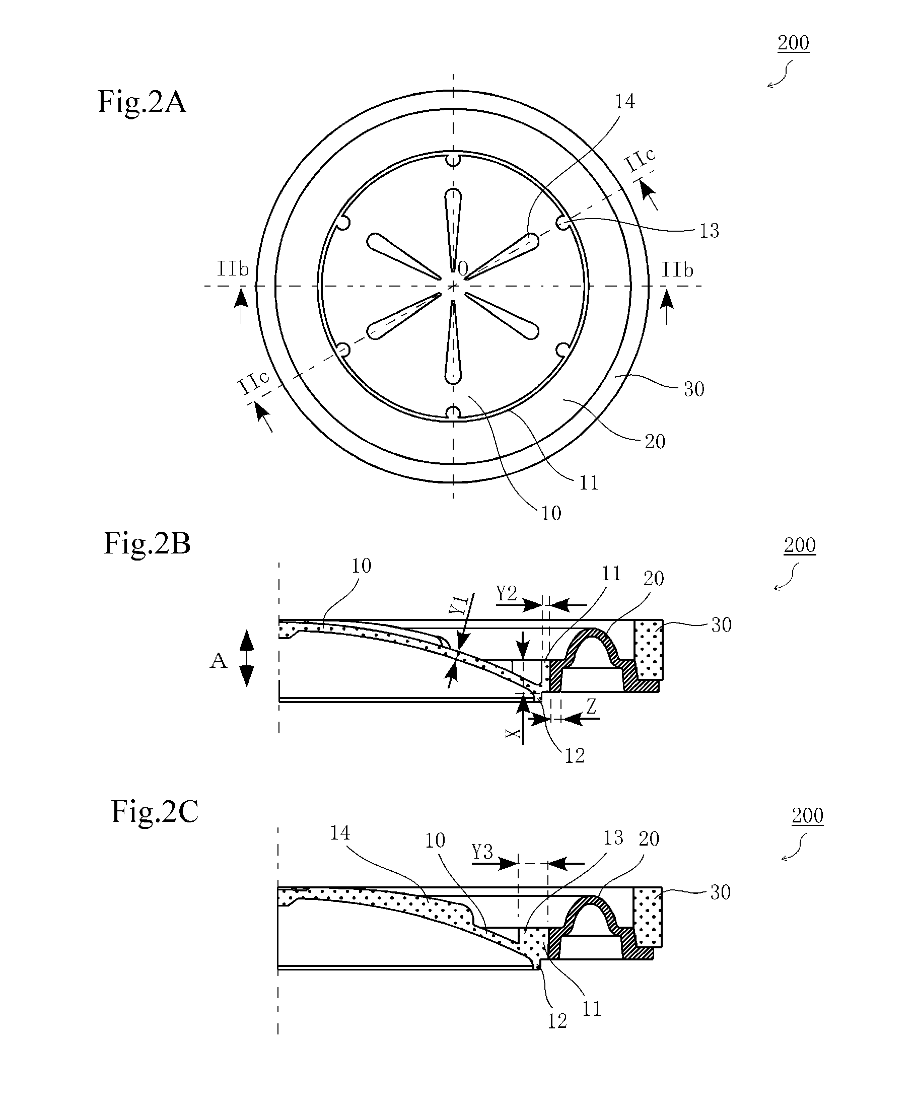
[0081]A loudspeaker diaphragm was produced according to the producing method illustrated in FIGS. 6A to 6C.

[0082]1. Primary Molding

[0083]The first die 71′ and the second die 72′ having cross-sectional shapes illustrated in FIGS. 6A to 6C were used (both the dies have an outermost diameter Φ of 19.2 mm). In a first cavity 1′ (diaphragm portion) and the third cavity 3 (gasket portion) formed by the dies, the diaphragm portion and the gasket portion were molded using a molding composition having a composition shown in Table 1 (FIG. 6A).

TABLE 1(Primary molding composition)Polypropylene resin70 partsMica25 partsCarbon black 5 parts

[0084]2. Secondary Molding

[0085]After the first die 71′ was released, a second cavity 2′ was formed by the second die 72′ and a third die 73′. In the second cavity 2′, the edge portion was molded using the composition for molding an edge portion (FIG. 6B). Then, the molded product was taken out of the dies (FIG. 6C), and thus a loudspeaker diaphragm ha...

Example

Example 2

[0089]A loudspeaker diaphragm and a loudspeaker were obtained in a similar way to that of Example 1, except that the primary molding composition having a composition shown in Table 2 was used.

TABLE 2(Primary molding composition)Resin pellet (manufactured by36 partsBiomass Technology Co., Ltd.,trade name “BT Pellet SRP70-3F”),which is obtained by mixing apolypropylene resin and non-foodstock rice in a weight ratio of30:70Resin pellet (manufactured by20 partsDaicel Polymer Ltd., trade name“PLASTRON PP-GF50-01”), which isobtained by mixing apolypropylene resin and longglass fiber (having a fiber lengthof 1 mm to 2 mm) in a weight ratioof 50:50Block polypropylene37 parts(manufactured by Prime PolymerCo., Ltd., trade name “PrimePolypro”)Deodorant masterbatch containing 5 parts10% of calcium stearateWater repellent masterbatch 2 partscontaining 10% of silicone

Example

Comparative Example 1

[0090]As illustrated in FIG. 7, a loudspeaker diaphragm was obtained in a similar way to that of Example 1, except that the diaphragm portion did not include the outer wall portion and a direction of the bonding portion between the diaphragm portion and the edge portion was along the diaphragm portion. Using the loudspeaker diaphragm thus obtained, a loudspeaker was obtained in a similar way to that of Example 1.


PUM


Abstract

A loudspeaker diaphragm according to an embodiment of the present invention includes: a diaphragm portion; and an edge portion, which is molded integrally with the diaphragm portion and made of a material different from a material for the diaphragm portion, wherein: the diaphragm portion includes, at an outer peripheral end thereof, an outer wall portion provided upright in a direction substantially parallel to a vibrating direction of the diaphragm portion; an inner peripheral surface of the edge portion is bonded onto an outer peripheral surface of the outer wall portion; and the outer wall portion has a height larger than a thickness of the diaphragm portion.

Description

[0001]This application claims priority under 35 U.S.C. Section 119 to Japanese Patent Application No. 2010-144605 filed on Jun. 25, 2010, which are herein incorporated by references.BACKGROUND OF THE INVENTION[0002]1. Field of the Invention[0003]The present invention relates to a loudspeaker diaphragm and a loudspeaker including the loudspeaker diaphragm.[0004]2. Description of the Related Art[0005]In general, a vibration system member, such as a loudspeaker diaphragm to be used in a loudspeaker, is obtained by assembling respective members, such as a diaphragm, an edge, and a gasket each molded into a predetermined shape, using an adhesive. The vibration system member thus obtained has a problem in that poor bonding may be caused depending on the combination of the respective members, and a problem in that characteristics may fluctuate due to a variation in adhesive application amount. Further, in order to prevent an operation failure of the loudspeaker, it is necessary to use a hi...

Claims


Application Information

Patent Timeline
IPC IPC(8): H04R1/00H04R7/00
CPCH04R7/12H04R7/18H04R2307/204H04R31/003H04R2307/025H04R9/06
Inventor FUJITANI, TAKESHIONO, YUSHITAKAHASHI, RYOICHISANO, RYOSUKE
Owner ONKYO KK
Why Eureka
Try Eureka