Eureka AIR delivers breakthrough ideas for toughest innovation challenges, trusted by R&D personnel around the world.

Bee Smoker

a smoke-generating device and bee-smoking technology, which is applied in the field of bee-smoking devices, can solve the problems of not disclosing the use of actual smoke, burning fires, and constant burning fires,

Inactive Publication Date: 2011-04-07
STEARNS DANIEL
View PDF57 Cites 8 Cited by
  • Summary
  • Abstract
  • Description
  • Claims
  • Application Information

AI Technical Summary

Benefits of technology

[0009]Another object of the invention is to provide a bee smoker in which heat and smoke are not generated when not needed.

Problems solved by technology

A drawback with conventional bee smokers is that the fire must be burning at all times in order for smoke to be available.
In addition, a constantly burning fire produces smoke and heat even when not needed.
However, Publication No. 20050262756 does not disclose the use of actual smoke.

Method used


Image

  • Bee Smoker
  • Bee Smoker
  • Bee Smoker

Examples


Embodiment Construction

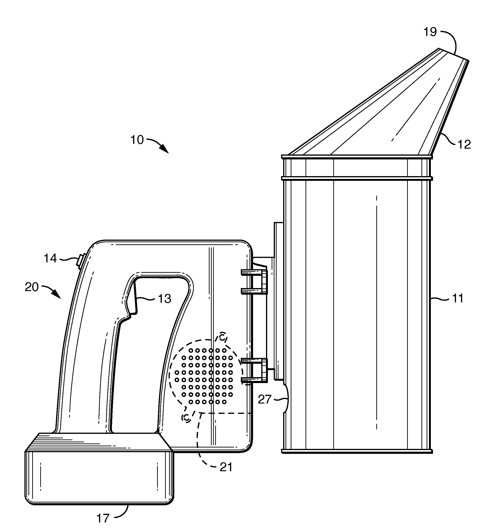
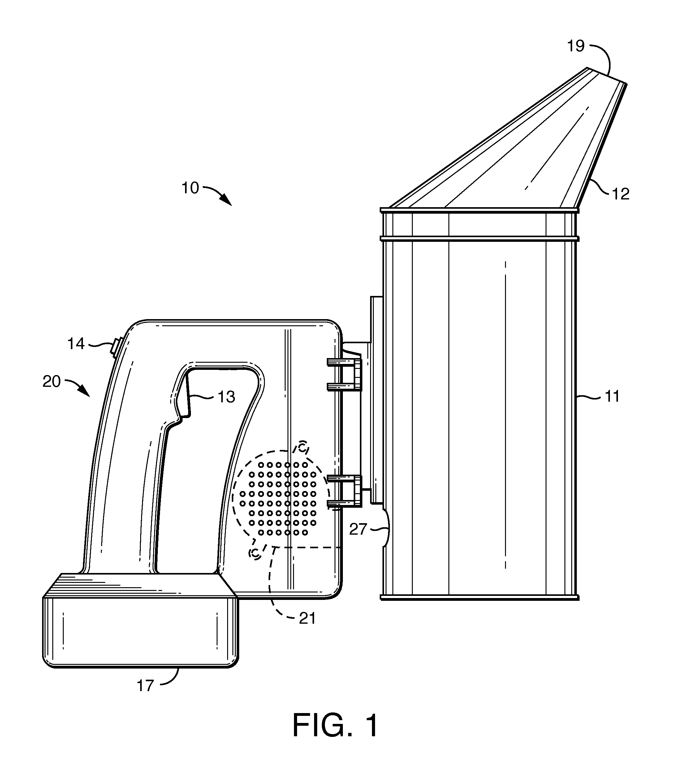
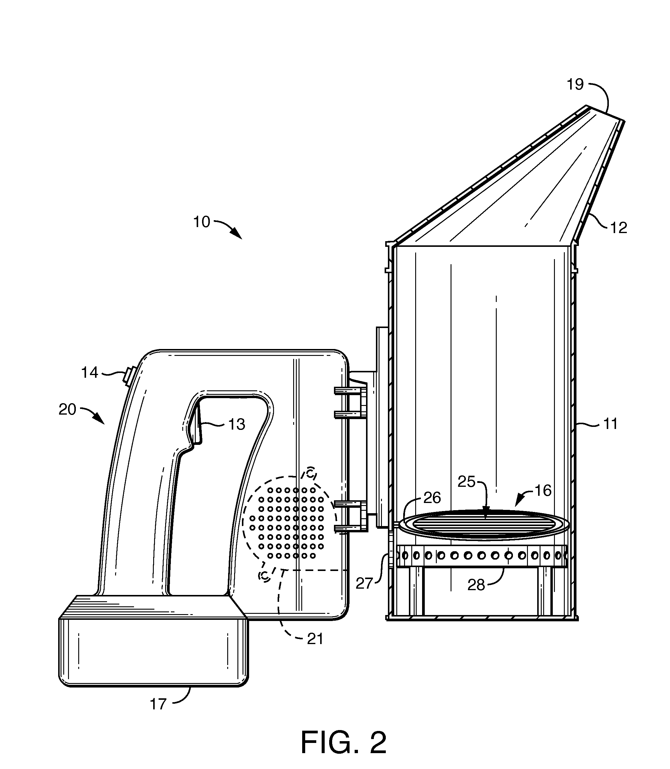
[0017]Bee smokers of the present invention can be of any size or shape provided that they can be carried by a bee keeper and they can be made of standard materials used for conventional bee smokers such as metal. The bee smoker 10 shown in FIG. 1 includes a housing 11 having a handle 20, a lid 12, and a spout 19. Housing 11 is preferably metal, but can also be made of any suitable heat and fire resistant material. The interior of housing 11 is accessible through lid 12 in the embodiment shown in FIG. 1, but side or bottom hatches are also possible. Bee smoker 10 as shown has two switches, smoke switch 13 and fan switch 14, which are shown positioned on handle 20 in the embodiment shown in FIG. 1.

[0018]Smoke switch 13 has ON and OFF positions. With smoke switch 13 in the ON position, smoke is generated in the bee smoker in a manner described below. In this way, a bee keeper can use bee smoker 10 to produce smoke when and as needed. When smoke switch 13 returns to the OFF position, sm...


PUM


Abstract

An improved bee smoker is provided for producing smoke on demand for use in controlling bees that includes a housing, a power source, a heating element, a fan, and switches.

Description

CROSS-REFERENCE TO RELATED APPLICATIONS[0001]None.STATEMENT REGARDING FEDERALLY SPONSORED RESEARCH OR DEVELOPMENT[0002]Not applicable.FIELD OF THE INVENTION[0003]This invention relates to hand-held smoke generating devices that can be used by bee keepers.BACKGROUND OF THE INVENTION[0004]Smoke can be used to control bees when bee keepers need to access the hive. Bee keepers have used bee smokers for centuries to create smoke for this purpose. Conventional bee smokers are hand-held devices that generally include a metal can with a lid, a spout, and a handle. A fire is started in the can using any materials that will burn to generate smoke. A pump can be used to bring air to the fire and to eject the smoke, which exits through the spout.[0005]A drawback with conventional bee smokers is that the fire must be burning at all times in order for smoke to be available. If the fire goes out, the bee keeper must re-light the fire, during which time no smoke will be available to control bees. I...

Claims


Application Information

Patent Timeline
Patent Type & Authority Applications(United States)
IPC IPC(8): A01K55/00
CPCA01K55/00
Inventor STEARNS, DANIEL
Owner STEARNS DANIEL
Why Eureka
Eureka Blog
Learn More