Dynamic External Fixator And Methods For Use

a fixator and external technology, applied in the field of use of dynamic external fixators, can solve the problems of little control over the movement of the wire and the amount of force on the bone, and the technique provides

Active Publication Date: 2011-04-07
STRYKER EURO OPERATIONS HLDG LLC
View PDF99 Cites 49 Cited by
  • Summary
  • Abstract
  • Description
  • Claims
  • Application Information

AI Technical Summary

Benefits of technology

[0009]For example, two pieces of a (traumatized) bone can be realigned by bringing the pieces of bone together. The bones are brought together by having a first and second k-wire pass through a first and second piece of the (traumatized) bone and having the first and second k-wires attached to one of a rigid body (e.g., ring element) or an adjustable device wherein the traumatized bone is realigned by moving the adjustable device in at least one axis. More specifically, after passing the first k-wire through the traumatized bone, both the first and second ends of the first k-wire are attached to a ring element. With the first piece of traumatized bone secured, a second k-wire is passed through a second piece of traumatized bone. After passing the second k-wire through the second piece of traumatized bone, the first end of the second k-wire is attached to a first adjustable device and the second end of the second k-wire is attached to a second adjustable device. Keeping the first k-wire attached to the rigid body the second k-wire can be moved in accurate multi axis movement by adjusting the first and second adjustable devices. Moving at least one of the first and second adjustable devices causes the second k-wire to move thereby moving the traumatized bone into a desired position (e.g., proper alignment).

Problems solved by technology

However, this technique provides little control over the movement of the wire and amount of force on the bone.

Method used


Image

  • Dynamic External Fixator And Methods For Use
  • Dynamic External Fixator And Methods For Use
  • Dynamic External Fixator And Methods For Use

Examples


Embodiment Construction

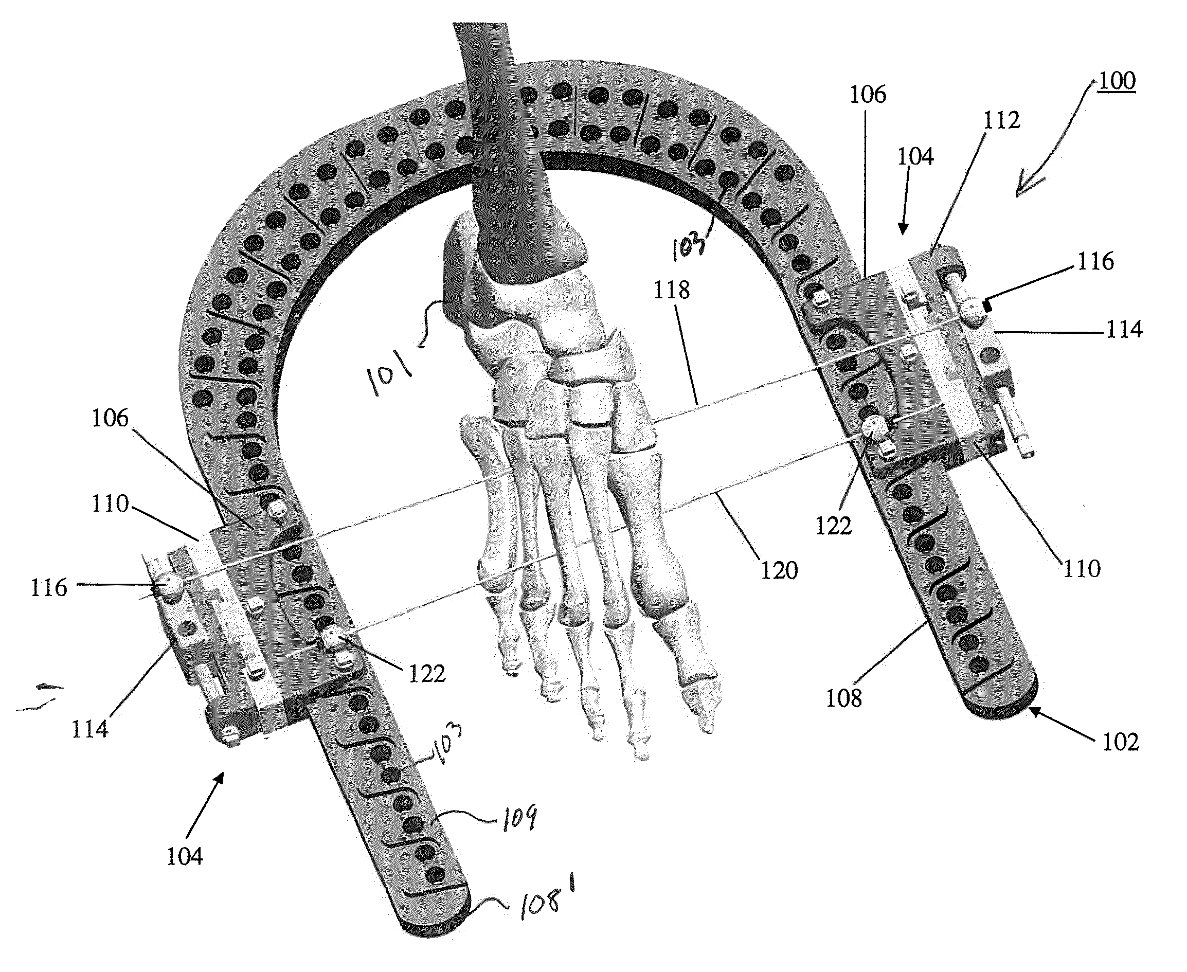
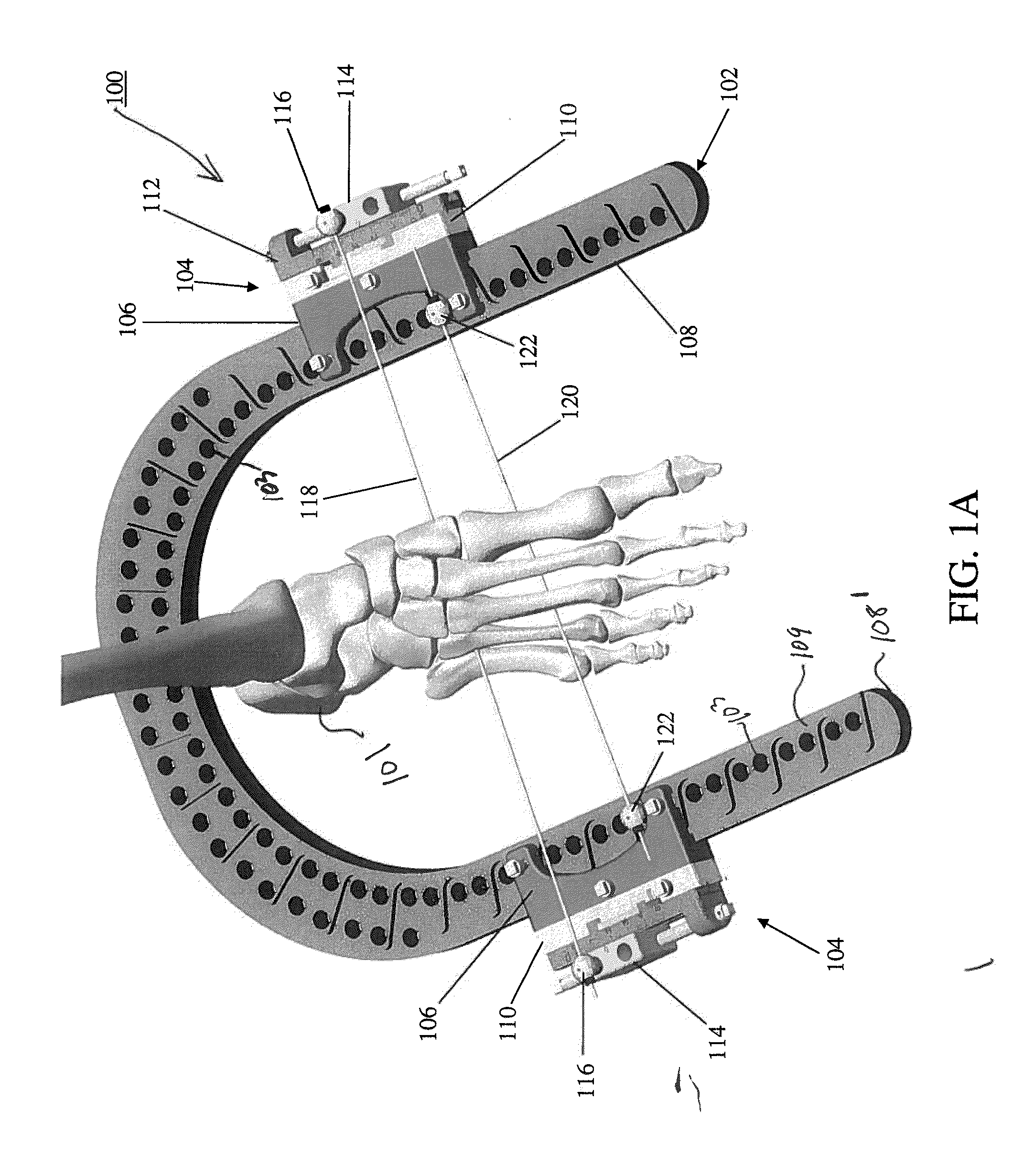
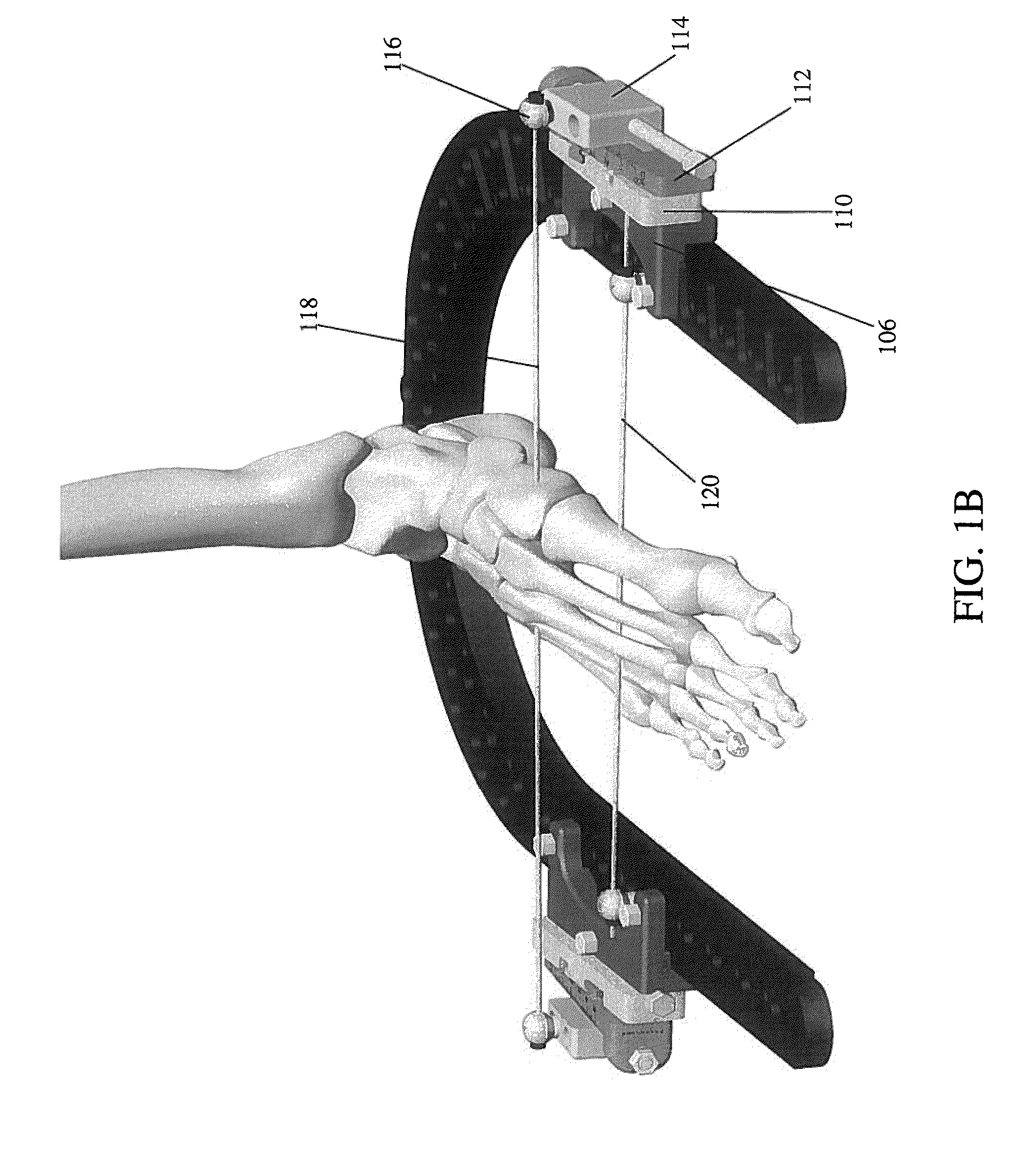
[0032]Referring to FIGS. 1A-1B, in accordance with a preferred embodiment of the present invention, an isometric view of a dynamic external fixator generally denoted as 100 is shown mounted on a foot 101 by pins. Dynamic external fixator 100 includes a U-shaped ring element 102 having a plurality of mounting holes 103 with at least one adjustable device 104, and preferably two, releasably attached to a pair of mounting holes 103. Adjustable device 104 includes a body 106 releasably attached to arms 108, 108′ of ring element 102. The adjustable device further includes a first member 110 slidably mounted on body 106 capable of providing movement in a direction perpendicular to a proximal surface 109 of arm 108, 108′ of ring element 102. Further, a second member 112 pivotally mounts on first member 110 for providing angular movement (i.e., rotation) with respect to first member 110. Further still, a third member 114 mounts on second member 112 providing linear movement along arms 108, ...


PUM


Abstract

An external fixation system and method for realigning, compressing or distracting broken bones has a planar ring element with an adjustable device having a body releasably mounted on the ring element. The adjustable device includes a first member for movement in a direction generally perpendicular to the ring element. A second member is pivotally connected to the first member for angular movement with respect to the ring. A third member is mounted on the second member for movement in a direction parallel to the second member and with respect to a circumference of the planar ring element. The method includes providing an external fixation system and inserting a k-wire through a first piece of bone and affixing the k-wire or half pin to the ring element. Then inserting a second k-wire or half pin through a second piece of bone and affixing the k-wire or half pin to an adjustable device. The pieces of bone are realigned, compressed or distracted by adjusting at least one of a first and second adjustable member forming the device.

Description

BACKGROUND OF THE INVENTION[0001]During reconstruction of a fractured or broken bone it is necessary to keep the repaired bone in an immobilized and stable state during the healing process. Further, the pieces of broken bones need to be encouraged to grow together. That is, the bone may be broken into multiple pieces and those pieces need to be moved together to promote proper healing. Presently, this is accomplished using a rigid body such as an external fixation ring or frame and various fixation components (e.g., wires, pins, etc.). These fixation components extend from the ring and immobilize the bone and move the bone into proper realignment.[0002]More specifically, the rigid body used in foot and / or ankle reconstruction is a foot frame. Typically, foot frames have an open ring member. This open ring member typically is a single U-shaped frame designed to connect with half pins or wires (e.g., Kirschner or k-wires) passed through the broken or fractured bones. To encourage the ...

Claims


Application Information

Patent Timeline
Patent Type & Authority Applications(United States)
IPC IPC(8): A61B17/00
CPCA61B17/6441A61B2017/564A61B17/88A61B17/62A61B17/645A61B17/848A61B2017/681
Inventor CROZET, YVES STEPHANEWALIA, GURVINDERJIT SINGHSINGH, MANOJ KUMAR
Owner STRYKER EURO OPERATIONS HLDG LLC
Why Eureka
Try Eureka