System for predicting the behavior of a transducer

a transducer and behavior technology, applied in the field of system for predicting the behavior of a transducer, can solve the problems of increased sound signal distortion, poor distortion reduction, nonlinear distortion of such transducers, etc., and achieve the effect of less complex circuitry and reduced nonlinear distortion

Active Publication Date: 2011-04-14
HARMAN BECKER AUTOMOTIVE SYST
View PDF20 Cites 15 Cited by
  • Summary
  • Abstract
  • Description
  • Claims
  • Application Information

AI Technical Summary

Benefits of technology

[0011]It is an object of the present invention to predict at least the mechanical, electrical, acoustical and / or thermal behavior of a transducer. It is a further object of the invention to reduce nonlinear distortions with less complex circuitry. It is a further object to overcome the detrimental effect of heat and power compression with transducers.
[0013]The model is used to perform appropriate compensation of a voltage signal supplied to the transducer in order to reduce non-linear distortions and power compression and provide a desired frequency response across a desired bandwidth at different drive levels. That is, the system compensates for adverse effects on the compression and frequency response of an audio signal in a loudspeaker due to voice coil temperature rising and nonlinear effects of the transducer. To accomplish this, a signal that is proportional to the voltage being fed to the loudspeaker may be used to predict at least the mechanical, electrical, acoustical and / or thermal behavior of the voice coil of the transducer, using a computerized model based on a differential equation system for the transducer.

Problems solved by technology

However, the sounds produced by such transducers comprise, in particular, nonlinear distortions.
However, if the system nonlinearities cannot be described by the second- and third-order terms of the series, the transducer will deviate from the model resulting in poor distortion reduction.
However, at higher levels the transducer deviates from the ideal second- and third-order model resulting in increased distortion of the sound signal.
However, perfect compensation requires an infinite number of terms and thus an infinite number of parallel circuit branches.
However, because of the complexity of elements required for circuits representing orders higher than third, realization of a practical solution is highly complex.
Another problem associated with electromagnetic transducers is the generation and dissipation of heat.
Thus, the power handling capacity of a transducer is limited by its ability to tolerate heat.
If more power is delivered to the transducer than it can handle, the transducer can burn up.
Another problem associated with heat generation is a temperature-induced increase in resistance, commonly referred to as power compression.
However, designing a high power speaker in this way results in very large and heavy speaker.
The systems disclosed by Button et al. are based on a linear loudspeaker model and provide compensation for power compression effects and but require relatively complex circuitry and show a strong dependency on the voice coil deviations.

Method used


Image

  • System for predicting the behavior of a transducer
  • System for predicting the behavior of a transducer
  • System for predicting the behavior of a transducer

Examples


Embodiment Construction

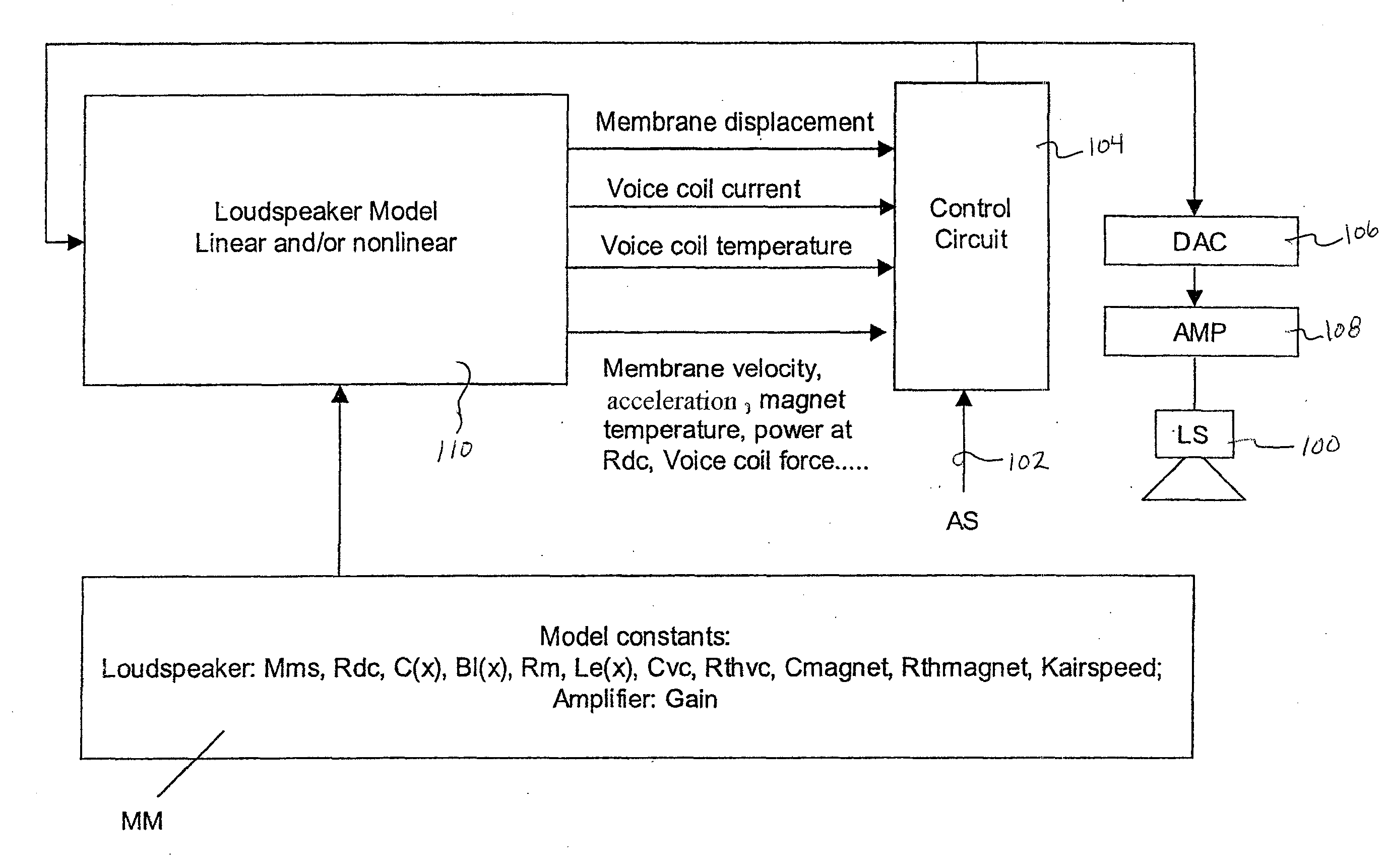
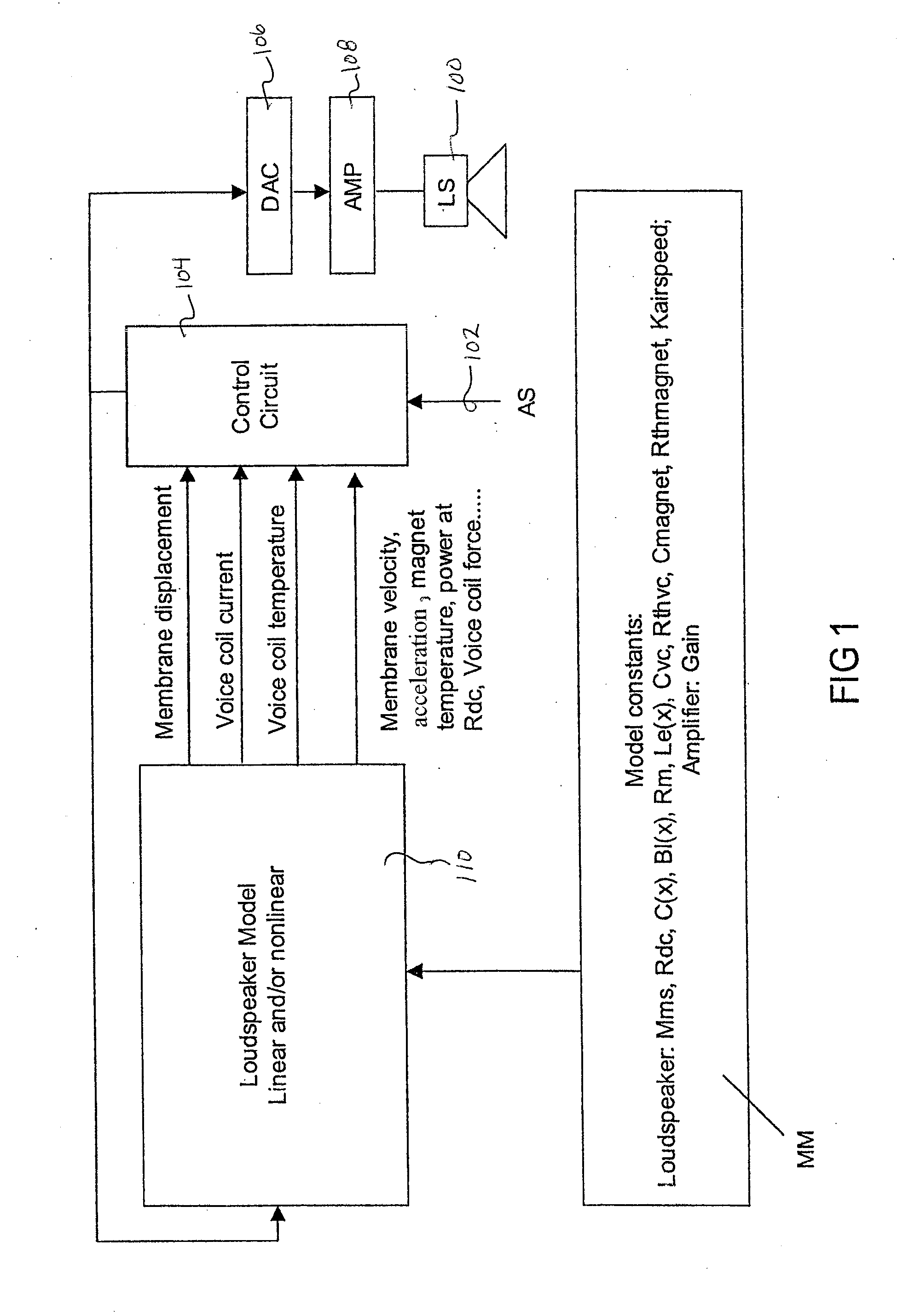
[0043]The present invention is further described in detail with references to the figures illustrating examples of the present invention. FIG. 1 shows a system for compensating for power loss and distortions (linear and non-linear) of a transducer such as a loudspeaker 100 having a magnet system with an air gap (not shown), and a voice coil movably arranged in the air gap (not shown) and supplied with an electrical input voltage. For the following considerations, for example, in terms of mass and cooling due to air flow et cetera, the diaphragm is considered part of the voice coil. A digital audio signal is supplied on a line 102 to the loudspeaker 100 via a control circuit 104, a digital-to-analog converter 106, and an analog amplifier 108. Instead of a combination of the digital-to-analog converter 106 and the analog amplifier 108, a digital amplifier providing an analog signal to the loudspeaker 100 may be used. In this embodiment, there is no feedback from the loudspeaker 100 to...


PUM


Abstract

A system for compensating and driving a loudspeaker includes an open loop loudspeaker controller that receives and processes an audio input signal and provides an audio output signal. A dynamic model of the loudspeaker receives the audio output signal, and models the behavior of the loudspeaker and provides predictive loudspeaker behavior data indicative thereof. The open loop loudspeaker controller receives the predictive loudspeaker behavior data and the audio input signal, and provides the audio output signal as a function of the audio input signal and the predictive loudspeaker behavior data.

Description

1. CLAIM OF PRIORITY[0001]This patent application is a divisional of co-pending U.S. Application No. 11 / 610,688 filed Dec. 14, 2006.2. FIELD OF THE INVENTION[0002]This invention relates to a system for predicting the behavior of a transducer using a transducer model, and then using that information to perform appropriate compensation of the signal supplied to the transducer to reduce linear and / or non-linear distortions and / or power compression, thus providing a desired frequency response across a desired bandwidth as well as protection for electrical and mechanical overloads.3. RELATED ART[0003]An electromagnetic transducer (e.g., a loudspeaker) uses magnets to produce magnetic flux in an air gap. These magnets are typically permanent magnets, used in a magnetic circuit of ferromagnetic material to direct most of the flux produced by the permanent magnet through the magnetic components of the transducer and into the air gap. A voice coil is placed in the air gap with its conductors...

Claims


Application Information

Patent Timeline
Patent Type & Authority Applications(United States)
IPC IPC(8): H04R3/00
CPCH04R3/08H04R29/001H04R29/00H04R3/007H04R3/04H04R3/00
Inventor PFAFFINGER, GERHARD
Owner HARMAN BECKER AUTOMOTIVE SYST
Why Eureka
Try Eureka