

Zoom lens for projection and projection-type display device
a technology of projection type and display device, which is applied in the field of zoom lens for projection and projection type display device, can solve the problems that neither of the zoom lens disclosed in patent document 1 and patent document 2 sufficiently satisfy, and achieve the effects of reducing the movement amount of each lens group, and reducing the deterioration of aberration balan
- Summary
- Abstract
- Description
- Claims
- Application Information
AI Technical Summary
Benefits of technology
Problems solved by technology
Method used
Image

Examples
example 1
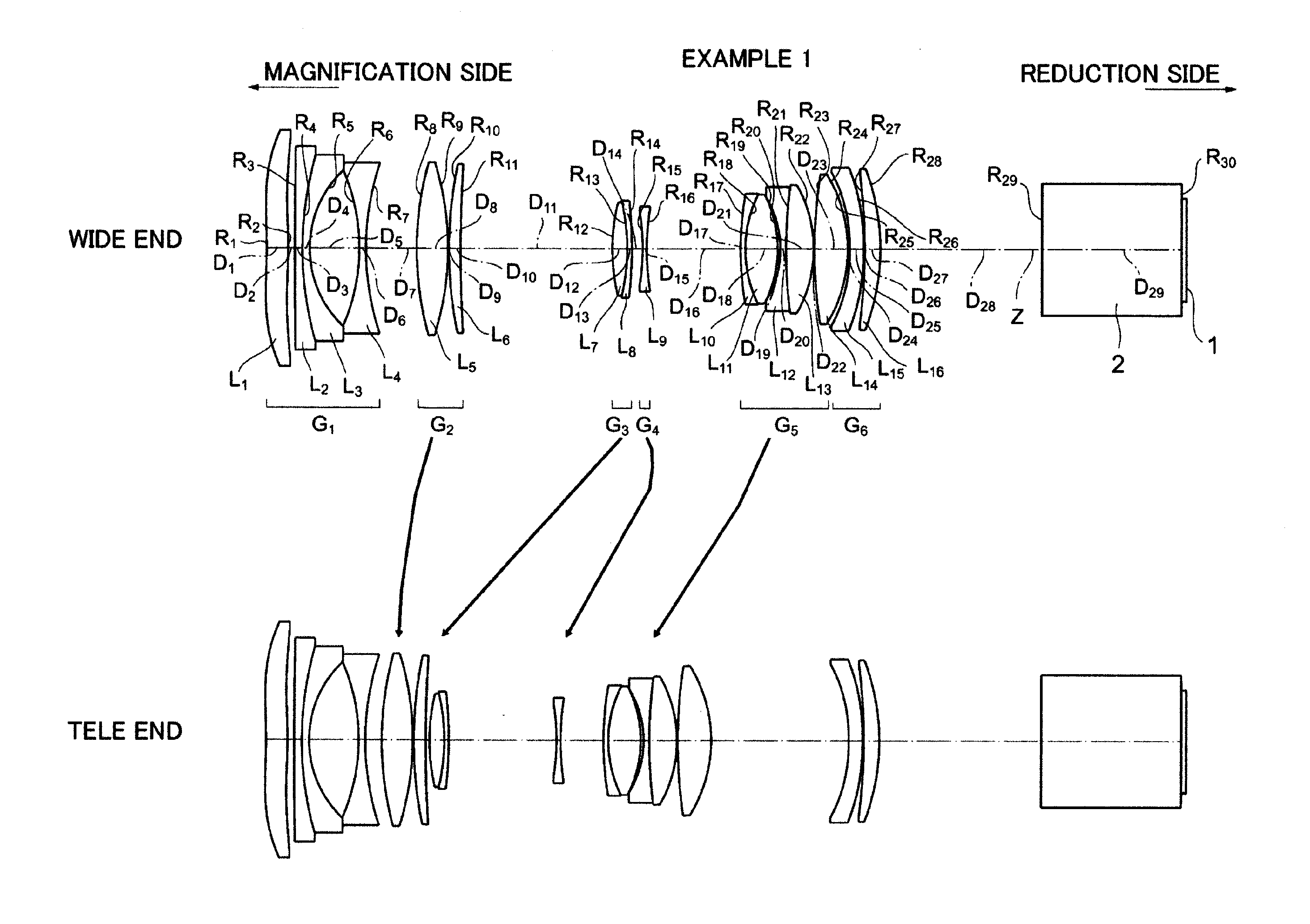
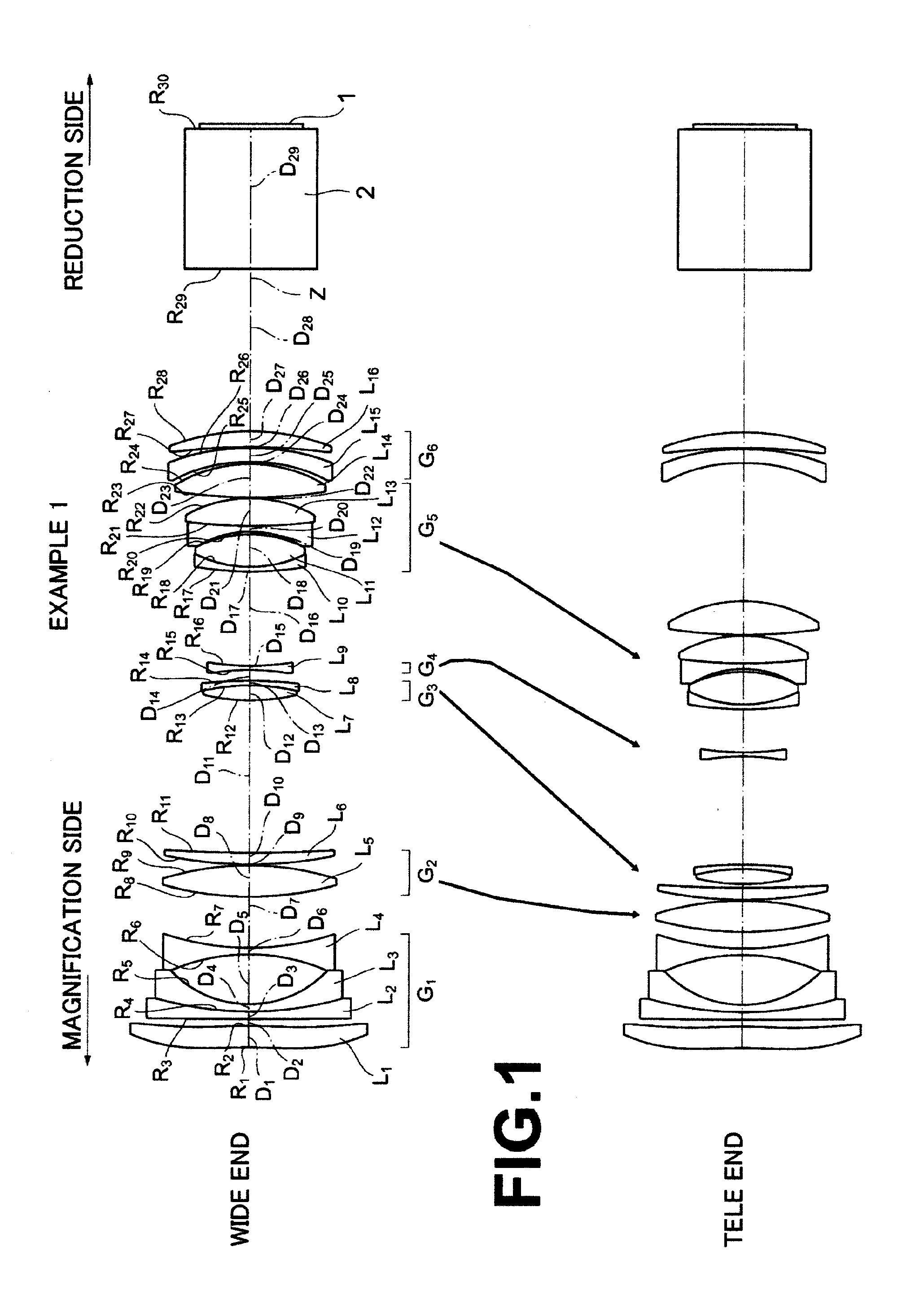
[0094]FIG. 1 is a diagram illustrating movement positions and movement paths of respective lens groups at a wide angle end (wide) and a telescopic end (tele) in a zoom lens for projection of Example 1.
[0095]In the zoom lens for projection of Example 1, first lens group G1 is composed of first lens L1, second lens L2, third lens L3, and fourth lens L4, which are arranged sequentially from the magnification side of the zoom lens for projection. The first lens L1 is a double-aspheric lens (aspheric-aspheric lens), both surfaces of which are aspheric, and has a weak power. The second lens L2 is a negative meniscus lens having a concave surface facing the reduction side. The third lens L3 is a negative meniscus lens having a concave surface facing the reduction side. The fourth lens L4 is a double-concave lens, both surfaces of which are concave. Further, the second lens L2 and the third lens L3 are cemented together to form a cemented lens.
[0096]Second lens group G2 is composed of fifth...
example 2
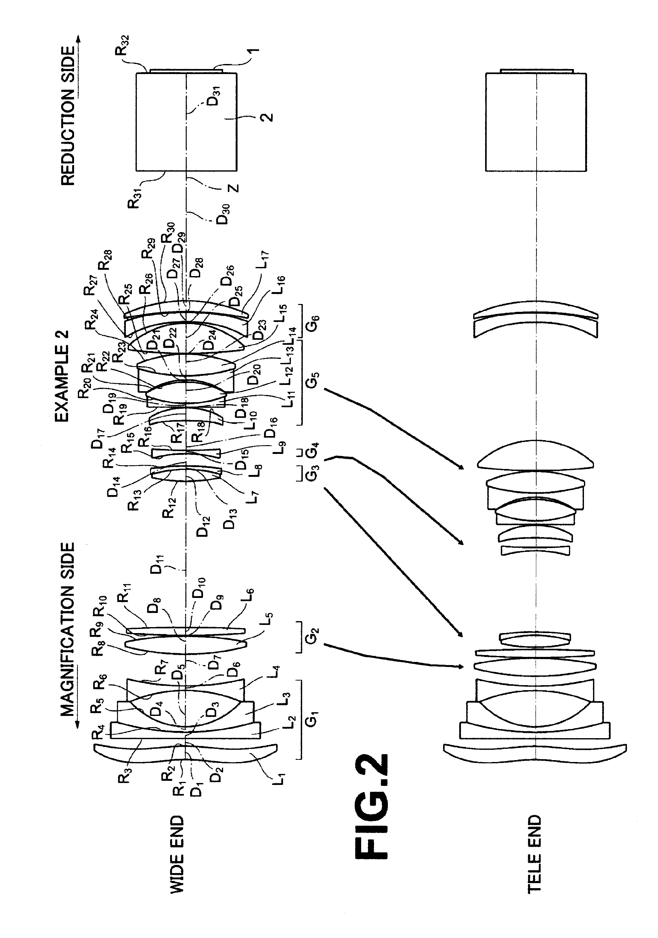
[0114]FIG. 2 is a diagram illustrating movement positions and movement paths of respective lens groups at a wide angle end (wide) and a telescopic end (tele) in a zoom lens for projection of Example 2.
[0115]The zoom lens for projection of Example 2 includes six lens groups in a manner basically similar to the zoom lens for projection of Example 1. However, the zoom lens for projection of Example 2 differs from the zoom lens for projection of Example 1 in that the second lens L2 in the first lens group G1 is a plano-concave lens, which has a flat surface and a concave surface, and that the sixth lens L6 in the second lens group G2 is a double-convex lens. Further, in the zoom lens for projection of Example 2, the fifth lens group G5 is composed of the tenth lens L10, eleventh lens L11, twelfth lens L12, thirteenth lens L13, fourteenth lens L14, and fifteenth lens L15, which are arranged sequentially from the magnification side, and the tenth lens L10 is a double-aspheric lens in posi...
example 3
[0123]FIG. 3 is a diagram illustrating movement positions and movement paths of respective lens groups at a wide angle end (wide) and a telescopic end (tele) in a zoom lens for projection of Example 3.
[0124]The zoom lens for projection of Example 3 includes six lens groups in a manner basically similar to the zoom lens for projection of Example 1. However, the zoom lens for projection of Example 3 differs from the zoom lens for projection of Example 1 in that the second lens L2 in the first lens group G1 is a double-concave lens, and that the second lens group G2 includes only the fifth lens L5, which is a double-convex lens. Further, in the zoom lens for projection of Example 3, the fifth lens group G5 is composed of the ninth lens L9, tenth lens L10, eleventh lens L11, twelfth lens L12, thirteenth lens L13, and fourteenth lens L14, which are arranged sequentially from the magnification side. The ninth lens L9 is a double-aspheric lens in positive meniscus form having a convex surf...
PUM
 Abstract
Description
Claims
Application Information