

Liquid crystal display device
a liquid crystal display and display device technology, applied in static indicating devices, instruments, non-linear optics, etc., can solve the problems of complex structure, transmission type liquid crystal display device contrast characteristic is easily degraded with respect to transmission type, and the transflective tba-mode liquid crystal display device has not been disclosed
- Summary
- Abstract
- Description
- Claims
- Application Information
AI Technical Summary
Benefits of technology
Problems solved by technology
Method used
Image

Examples
embodiment 1
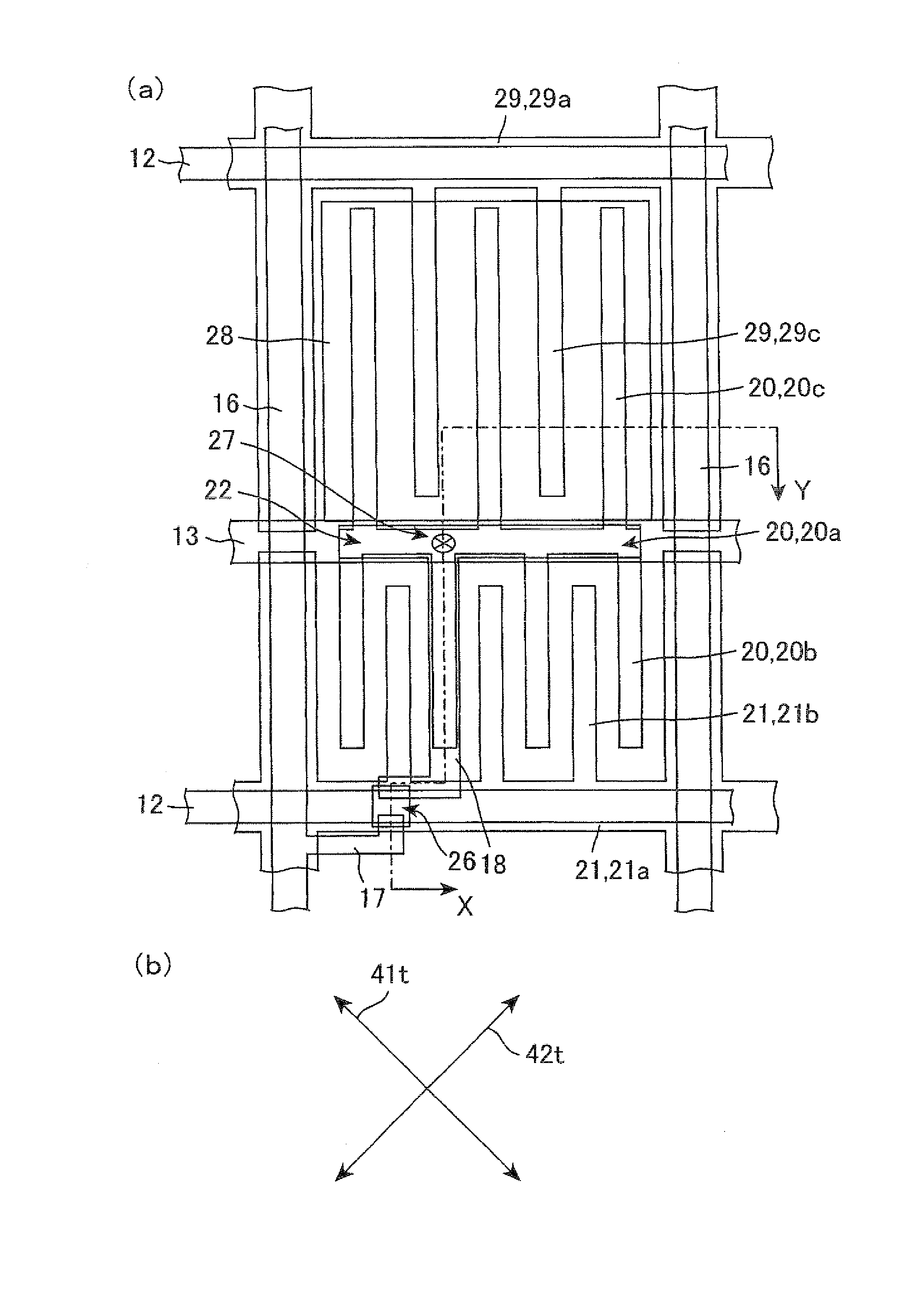
[0037]A liquid crystal display device of the present embodiment is of a transflective type that uses the so-called TBA system of transverse field systems in which image display is performed by causing an electric field (transverse electric field) in the direction of substrate plane to act upon a liquid crystal layer and controlling the alignment.
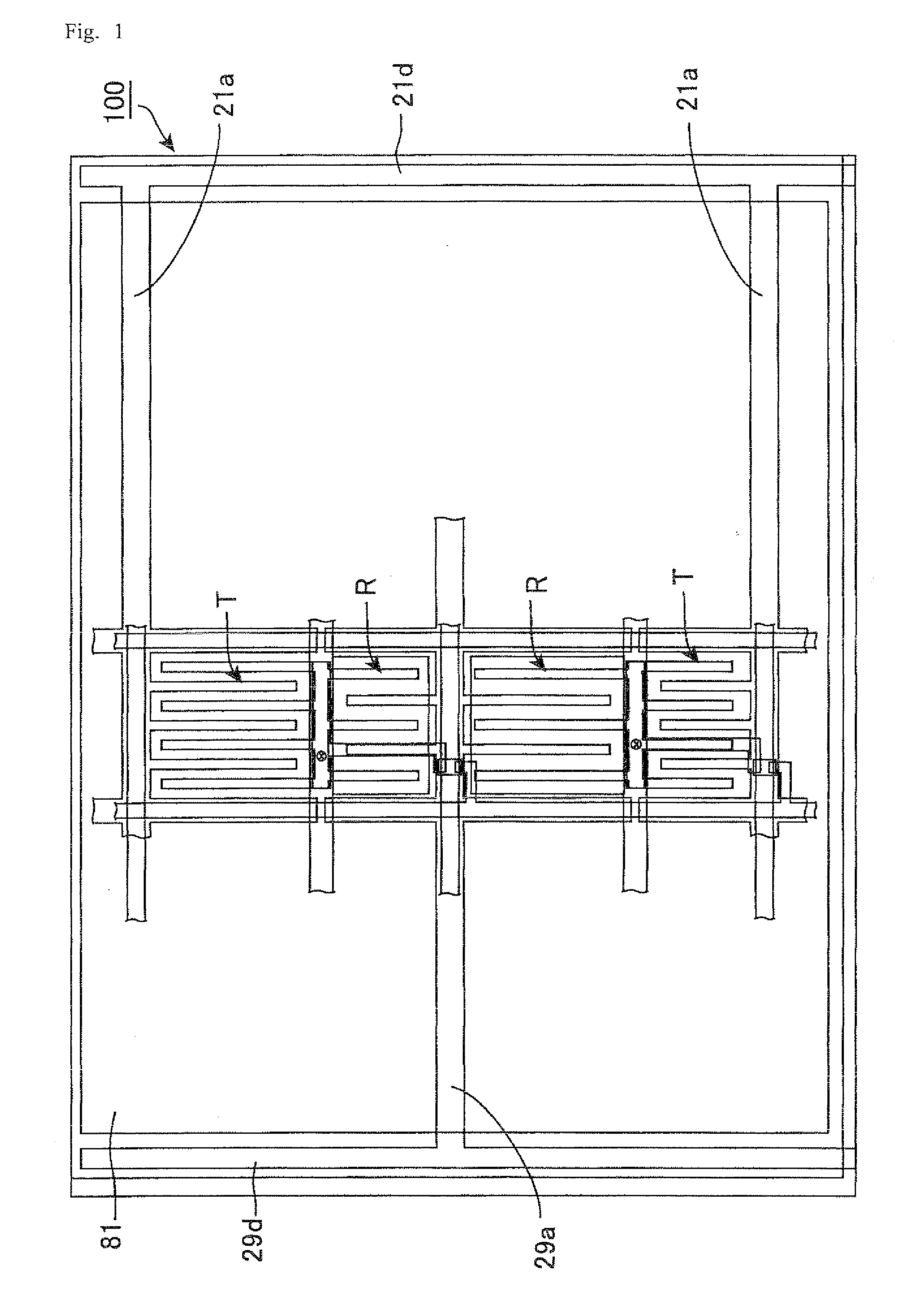
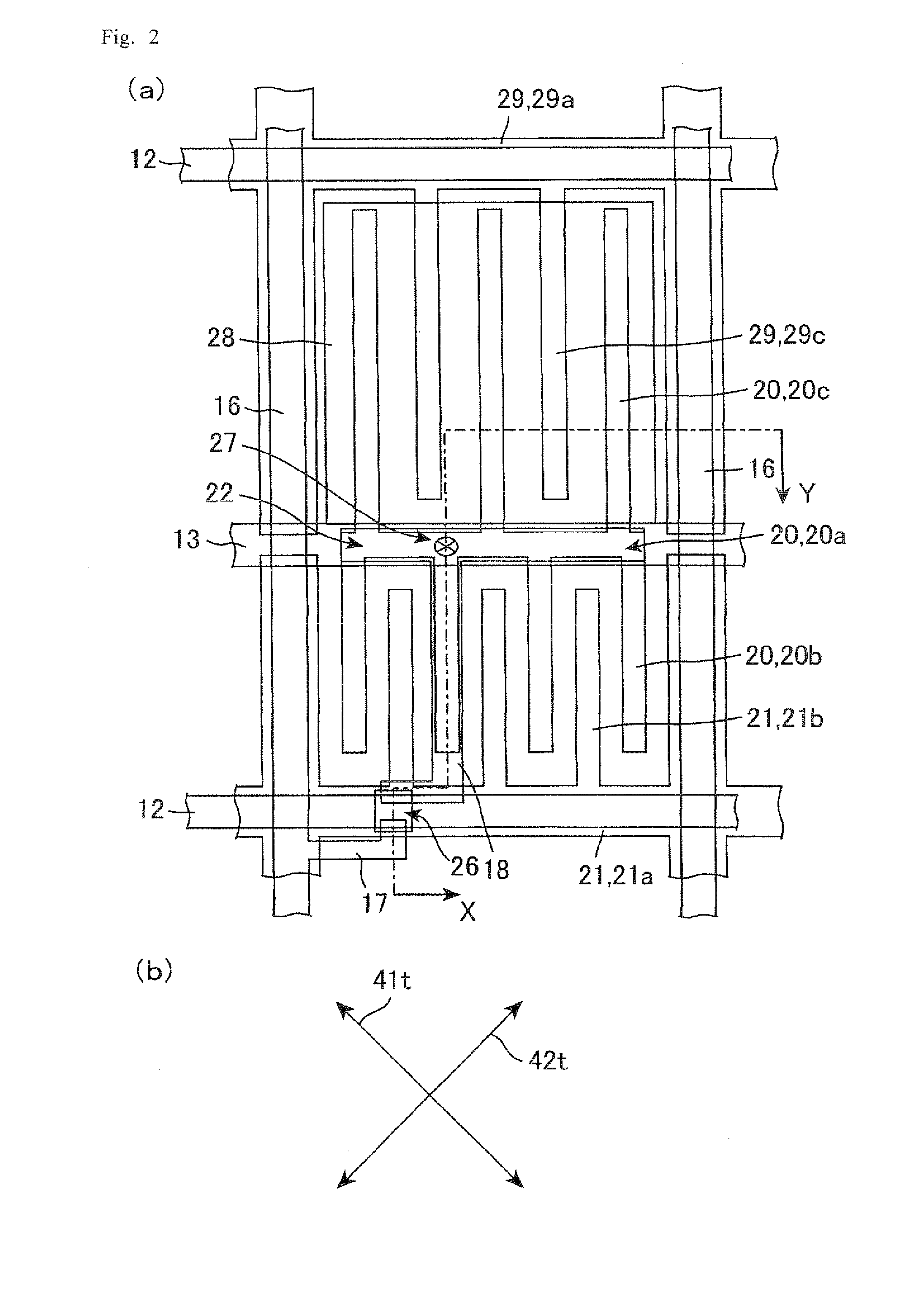
[0038]FIG. 1 is a plan schematic view illustrating the configuration of a liquid crystal display panel of Embodiment 1. FIG. 2(a) is a plan schematic view illustrating the configuration of one sub-pixel of the liquid crystal display panel of Embodiment 1. FIG. 2(b) is a schematic diagram illustrating mutual arrangement of transmission axes of polarizing plates in Embodiment 1. FIG. 3 is a cross-sectional schematic diagram illustrating the configuration of the liquid crystal display panel of Embodiment 1; this figure shows a cross section taken along line X-Y in FIG. 2(a). FIG. 4 is a plan schematic view illustrating the circuit configuration...
PUM
| Property | Measurement | Unit |
|---|---|---|
| widths | aaaaa | aaaaa |
| angle | aaaaa | aaaaa |
| angle | aaaaa | aaaaa |
Abstract
Description
Claims
Application Information