
Method of controlling alignment of an optical wireless communication link

a technology of optical wireless communication and alignment method, applied in electromagnetic transmission, electrical apparatus, transmission, etc., can solve problems such as providing high bandwidth links, and achieve the effect of high bandwidth links

Active Publication Date: 2006-05-02
TEXAS INSTR INC
View PDF1 Cites 0 Cited by
  • Summary
  • Abstract
  • Description
  • Claims
  • Application Information

AI Technical Summary

Benefits of technology

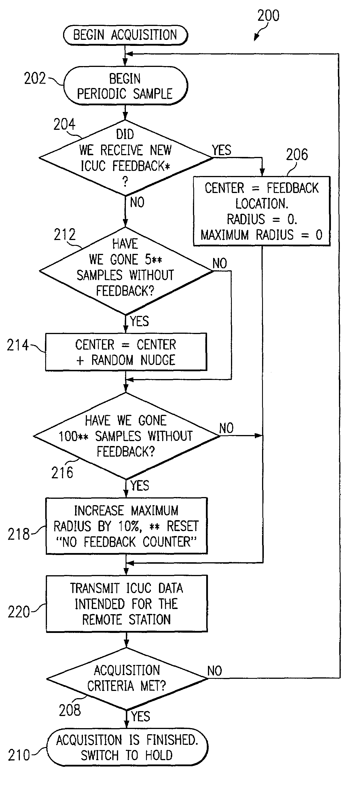
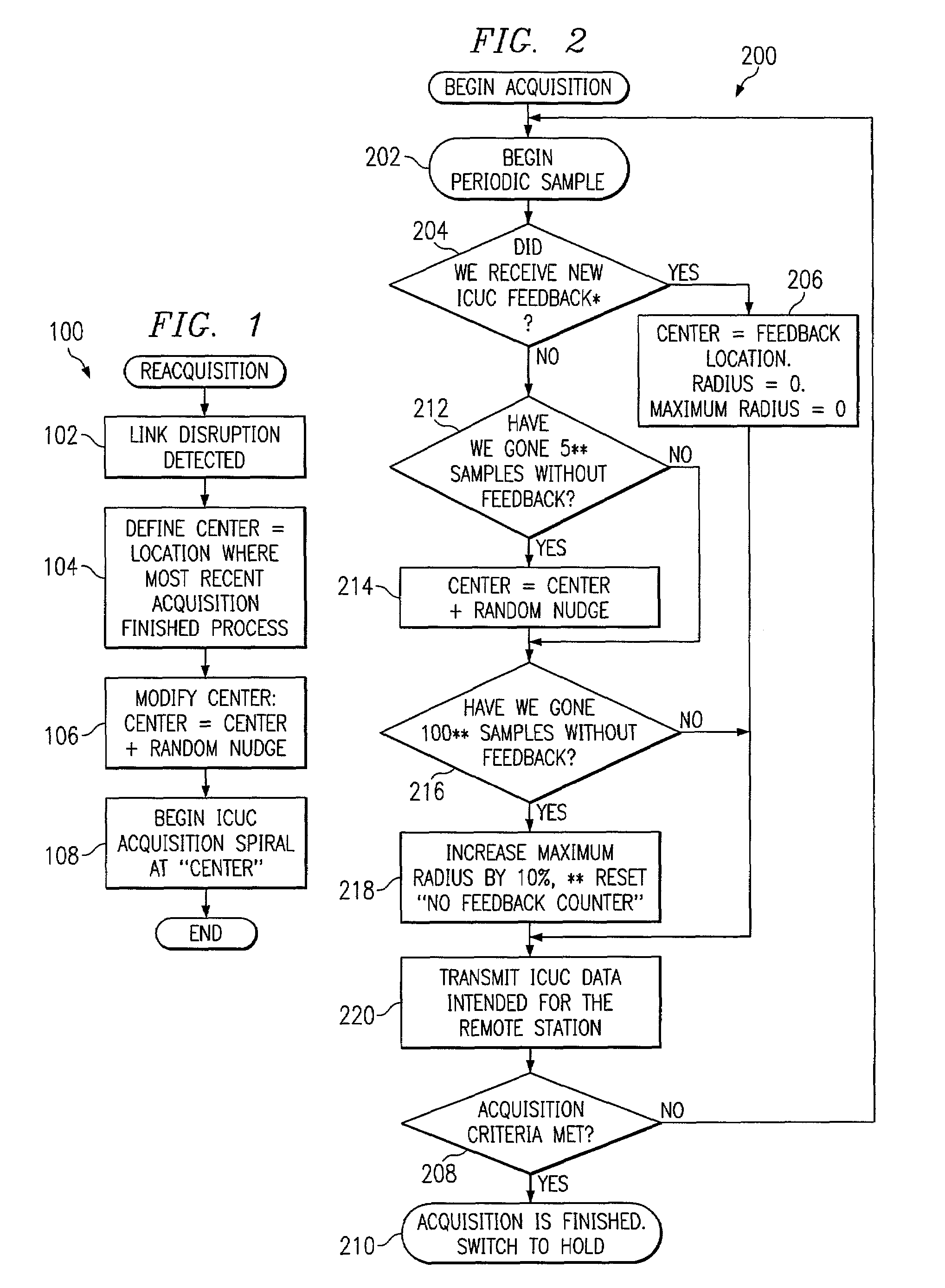
[0008]The present invention is directed to a method of controlling alignment of an optical wireless communication link between two optical transceivers. The method allows an optical wireless communication link between the stations to be used reliably without the need for position sensing capabilities simply by modifying acquisition and re-acquisition algorithms such as those defined in U.S. patent application Ser. No. 09 / 940,763 and U.S. patent application Ser. No. 09 / 942,265 referenced herein before. The '763 and '265 patent applications are assigned to Texas Instruments Incorporated, the assignee of the present application, and are incorporated by reference in their entirety herein. Randomly modifying the center of the acquisition spiral that is used for a scan pattern by a small amount (for example, a fraction of the beam divergence) has the effect of moving away from locations where the alignment is sufficient to feedback some positional data, but not enough to provide a high bandwidth link. “Sensorless acquisition” has been successfully demonstrated by the present inventor at distances ranging from 1 to 50 meters using this random nudge technique. This random nudge technique can be used at different times during the wireless communication process.
[0009]In one aspect of the invention, a method of controlling alignment of an optical wireless communication link between an optical transmitting station and an optical receiving station is implemented by randomly adjusting the center of the spiral used for a scan pattern during the final signal acquisition cycle. Using this aspect, the initial alignment between the stations can be performed at a much faster rate. For example, by applying the nudge if more than a couple samples in a row are missed, the algorithm will not dwell in locations which have poor error rates.
[0010]In another aspect of the invention, a method of controlling alignment of an optical wireless communication link between an optical transmitting station and an optical receiving station is implemented by randomly adjusting the starting point of the center of the spiral used for a scan pattern during a signal re-acquisition cycle. Using this aspect, will prevent the stations from the endless cycle between “hold” and “acquisition”.

Problems solved by technology

Randomly modifying the center of the acquisition spiral that is used for a scan pattern by a small amount (for example, a fraction of the beam divergence) has the effect of moving away from locations where the alignment is sufficient to feedback some positional data, but not enough to provide a high bandwidth link.

Method used


Image

  • Method of controlling alignment of an optical wireless communication link
  • Method of controlling alignment of an optical wireless communication link

Examples


Embodiment Construction

[0015]The preferred embodiments are best explained by first considering the case in which the transmitting and receiving units have first completed a coarse acquisition process. During the coarse acquisition process, signals are monitored to determine if any new feedback information is received. This feedback information may be monitored using an “ICUC” (“I see, you see”) acquisition spiral which spirals in and out, transmitting both its local position as it goes, along with the most recent value of the remote that it has seen. The spiral is therefore transmitting what “I see” and the remote is transmitting what “you see”. Upon completion of the coarse acquisition, a determination must then be made as to when the receiving stations should drop into a “hold” mode. Since positioning accuracy cannot be monitored, some other criteria must be used to make this determination. Continued use of the ICUC spiral acquisition method until a predetermined number of consecutive sightings count is...


PUM


Abstract

A method that allows an optical wireless communication link between transmitting and receiving stations to be established and used reliably without the need for position sensing capabilities. A small random nudge of the center of the acquisition spiral is used to prevent a link from being established before proper alignment is attained or to correct the alignment of an established link which does not have sufficient alignment to maintain a high bandwidth link.

Description

RELATED APPLICATIONS[0001]This patent application is related to U.S. patent application Ser. No. 09 / 940,763, entitled Method And Apparatus For Aligning Optical Wireless Link, filed on Aug. 27, 2001 by Heminger et al., claiming benefit of Provisional Application Ser. No. 60 / 285,461, filed on Apr. 20, 2001; and also U.S. patent application Ser. No. 09 / 942,265, entitled Method And Apparatus For Re-Acquisition After Link Disruption In An Optical Wireless Link, filed on Aug. 27, 2001 by Oettinger et al., claiming benefit of Provisional Application Ser. No. 60 / 285,460, filed on Apr. 20, 2001.BACKGROUND OF THE INVENTION[0002]1. Field of the Invention[0003]This invention relates generally to wireless communications systems, and more particularly, to a method of controlling alignment of an optical wireless communication link between an optical transmitting station (transceiver) and an optical receiving station (transceiver) which are not capable of sensing positional information of the remot...

Claims


Application Information

Patent Timeline
IPC IPC(8): H04B10/00H04B10/10
CPCH04B10/1149H04B10/1123
Inventor OETTINGER, ERIC G.
Owner TEXAS INSTR INC
Learn More