Imprinting Transfer Roll

a transfer roll and resin technology, applied in the direction of photomechanical equipment, instruments, separation processes, etc., can solve the problems of poor versatility, affecting the smoothness of the transfer object, and the difference in level, so as to achieve the effect of easy control of the alignment of the resin mold with the transfer object resin

Inactive Publication Date: 2017-04-20
SOKEN CHEM & ENG CO LTD
View PDF0 Cites 0 Cited by
  • Summary
  • Abstract
  • Description
  • Claims
  • Application Information

AI Technical Summary

Benefits of technology

[0019]According to the present invention, a resin mold can be set at the accurate position on a roll and fixed thereto by a simple method comprising sandwiching one end of a resin film substrate having a resin mold affixed thereto between two divided bodies obtained by dividing a roll body into two and preferably inserting a pin provided on one divided body into a mounting hole provided in the above one end part of the resin film substrate. As a result, alignment of the resin mold with a transfer object resin can be readily controlled. Moreover, a difference in level is not formed on the resin film substrate and the resin mold during the fixing process.

Problems solved by technology

However, when a pressure-sensitive adhesive tape is used in such a manner, there are a problem of occurrence of a difference in level attributable to the pressure-sensitive adhesive tape and a problem that the alignment of the mold with a transfer object resin varies for each production lot because the adhesion position on the roll in the width direction of the roll and the adhesion angle to the roll cannot be accurately determined.
In this method, however, the recessed-protruded pattern is formed by electroforming and has poor versatility.
In this method, however, it is necessary to provide chuck portions having magnetic force in order to fix the film having a resin mold affixed thereto, and therefore, much time and labor are needed to prepare the device.

Method used


Image

  • Imprinting Transfer Roll
  • Imprinting Transfer Roll
  • Imprinting Transfer Roll

Examples


Embodiment Construction

[0025]The imprinting transfer roll according to a preferred embodiment of the present invention will be described hereinafter referring to the attached drawings.

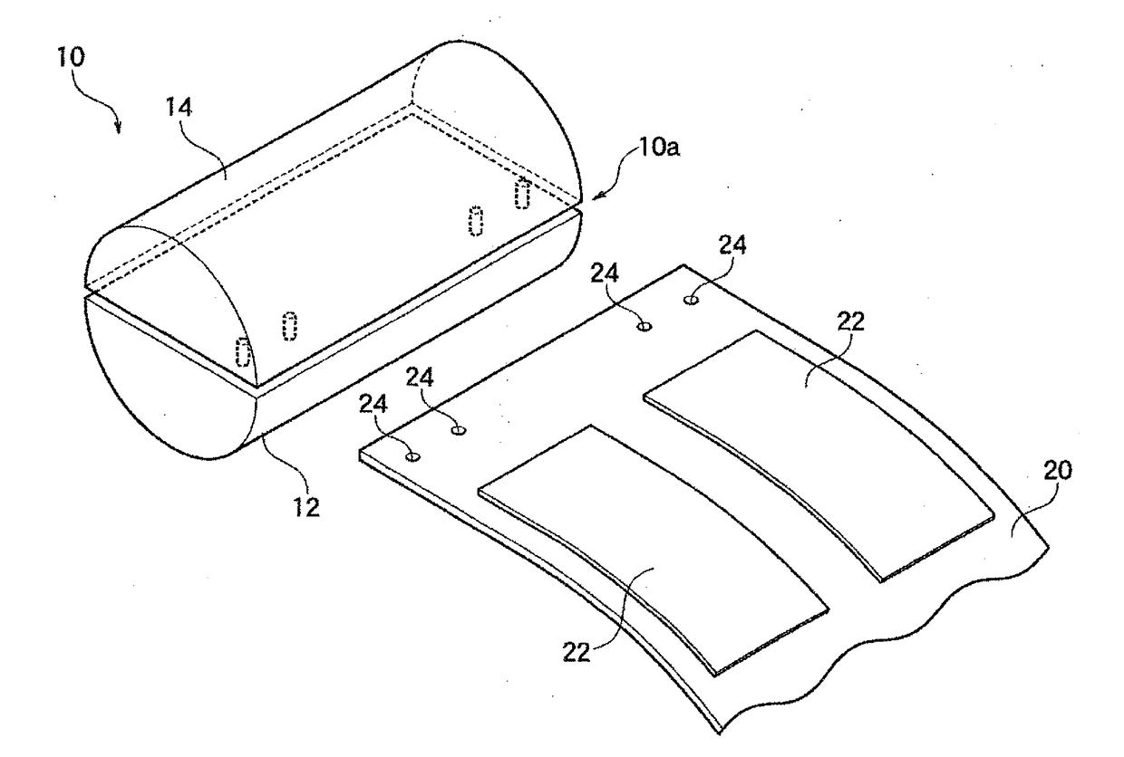
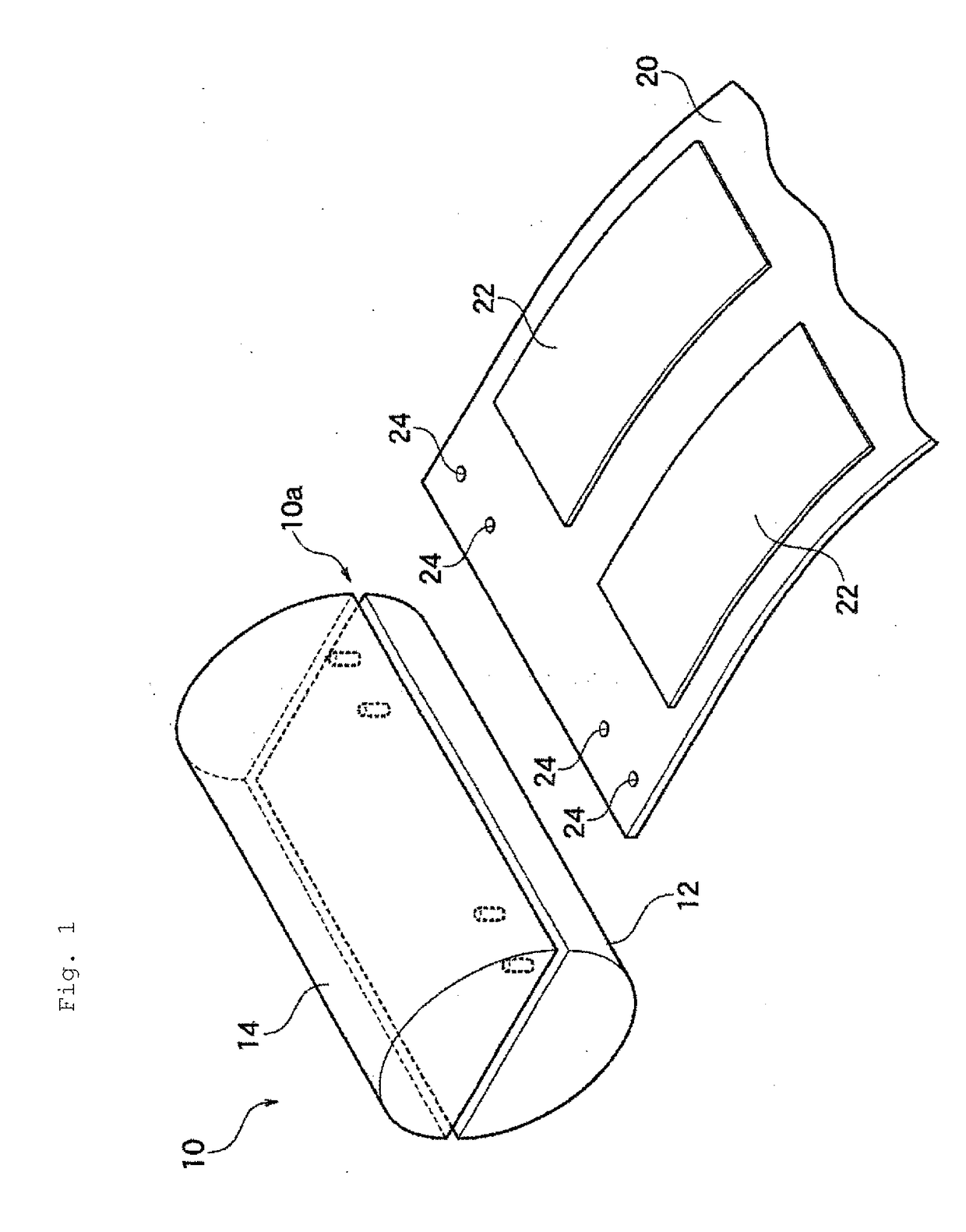
[0026]The imprinting transfer roll of the present invention is an imprinting transfer roll comprising a roll body around a peripheral surface of which a resin film substrate is to be wound, to said resin film substrate a resin mold having a fine recessed-protruded pattern formed on its surface having been affixed, wherein:

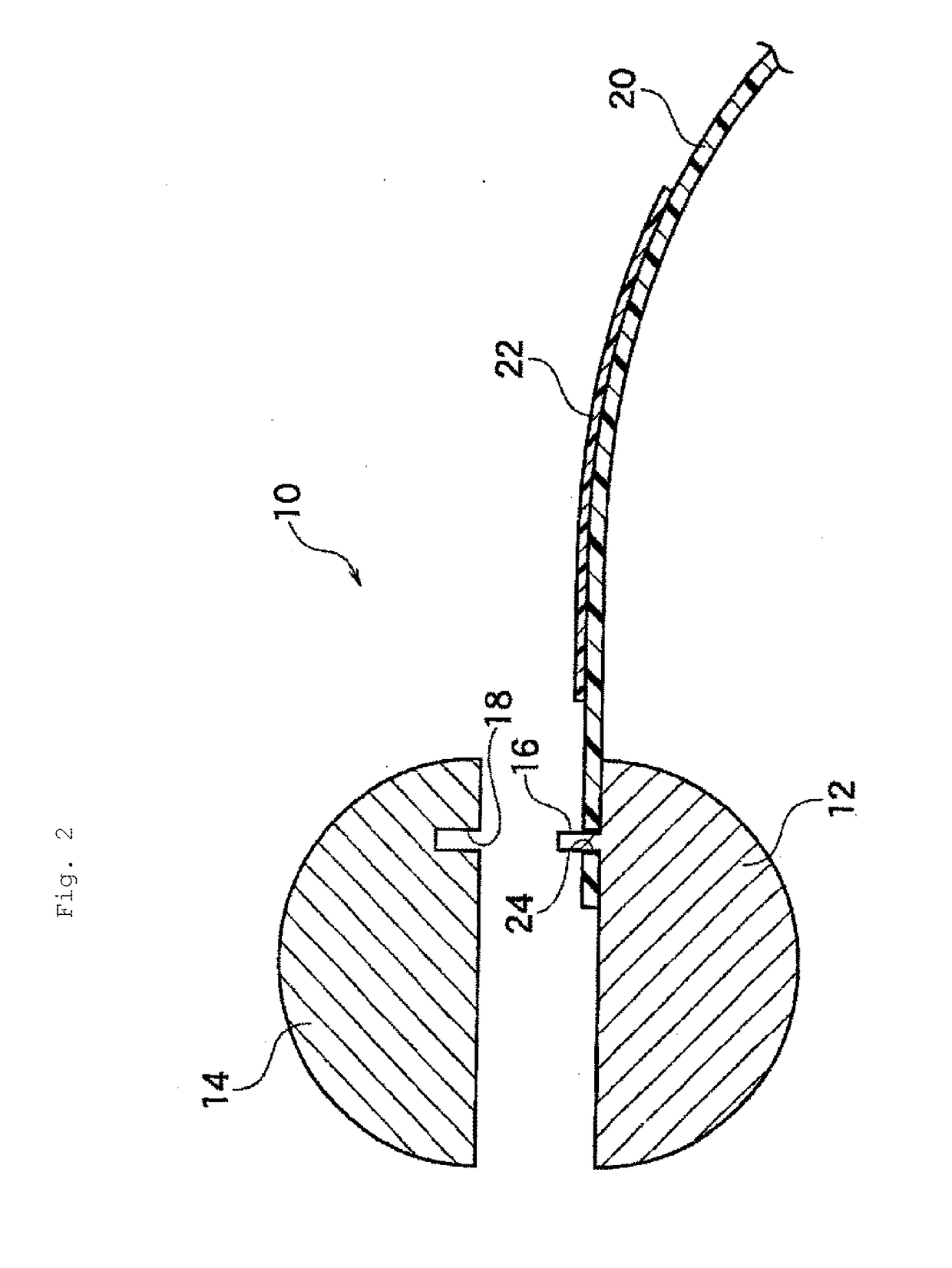
[0027]the roll body is divided into two and thereby constituted of one divided body and the other divided body, and between divided faces of these first divided body and second divided body to be joined together, one end of the resin film substrate is to be sandwiched to integrate the first divided body and the second divided body, and then the resin film substrate is to be wound around in the circumferential direction of the roll body.

[0028]FIG. 1 to FIG. 4 each show an imprinting transfer roll according t...


PUM

PropertyMeasurementUnit
angleaaaaaaaaaa
thicknessaaaaaaaaaa
thicknessaaaaaaaaaa

Abstract

Provided is a resin mold which is fixed to an accurate position on a roll for use in an imprinting device of roll transfer system by a simple method and thereby facilitates control of alignment of the resin mold with a transfer object resin. The imprinting transfer roll is an imprinting transfer roll including a roll body around a peripheral surface of which a resin film substrate is to be wound, to said resin film substrate a resin mold having a fine recessed-protruded pattern formed on its surface having been affixed, wherein the roll body is divided into two and thereby constituted of one divided body and the other divided body, and between divided faces of these first divided body and second divided body to be joined together, one end of the resin film substrate is to be sandwiched to integrate the first divided body and the second divided body, and then the resin film substrate is to be wound around in the circumferential direction of the roll body.

Description

TECHNICAL FIELD[0001]The present invention relates to an imprinting transfer roll for use in an imprinting device.BACKGROUND ART[0002]Nanoimprinting technique is a technique to press a mold having a recessed-protruded pattern formed thereon against a liquid resin or the like on a substrate to transfer the pattern of the mold to the resin. As recessed-protruded patterns, patterns ranging from nanoscale patterns of 10 nm level to patterns of about 100 μm are present, and they are used in various fields, such as fields of semiconductor materials, optical materials, storage media, micromachines, biotechnology and environment.[0003]Devices for use in the nanoimprinting technique include devices of roll transfer system, such as a device of so-called roll-to-plate system to transfer the shape of a mold on a roll to a resin on a flat substrate and a device of so-called roll-to-roll system to transfer the shape of a mold on a roll to a resin on a roll.[0004]For fixing a mold to a roll in the...

Claims


Application Information

Patent Timeline
Patent Type & Authority Applications(United States)
IPC IPC(8): B29C59/04B29C59/00
CPCB29C59/04B29C2059/023B29L2007/008B29C59/002B29C33/38B32B37/0053B32B38/06B01D59/04G03F7/0002B29C2043/025
Inventor MIZUKAMI, YUTAKA
Owner SOKEN CHEM & ENG CO LTD
Why Eureka
Try Eureka